Please note, these instruction are for the second version (v.2) of the multiboard. Instructions for the first version of the board are here.
For a beginner, this is not the quickest of builds, but there’s really nothing tricky about it either since the board uses through-hole components exclusively and all the components are on the same side of the board. If you’ve never soldered through-hole electronics before, I suggest you give yourself a quick primer with one of the numerous through-hole soldering tutorials on YouTube, like this one.
Importantly, take all the time you need – there’s no rush. And work in a well-ventilated space.
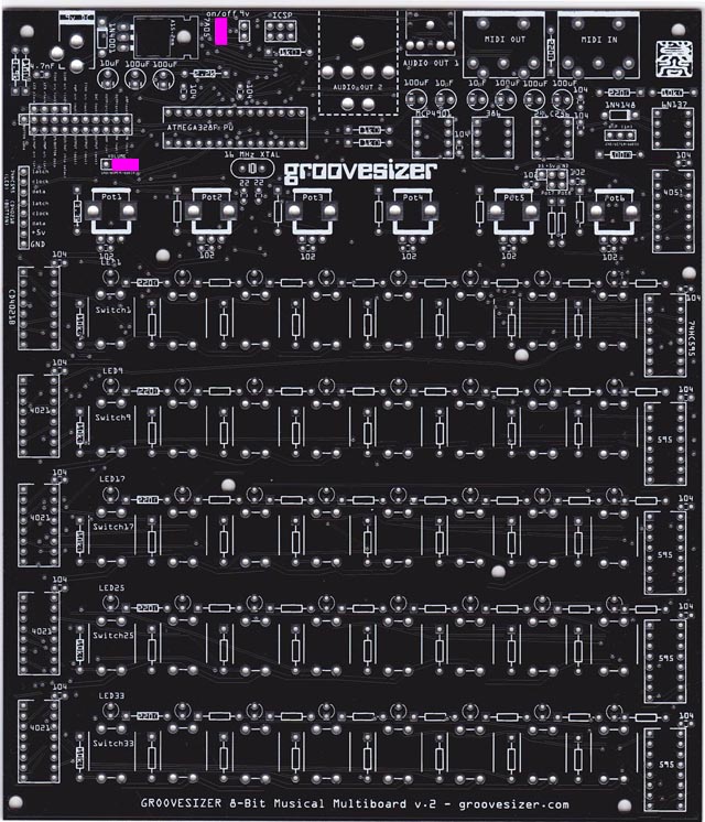
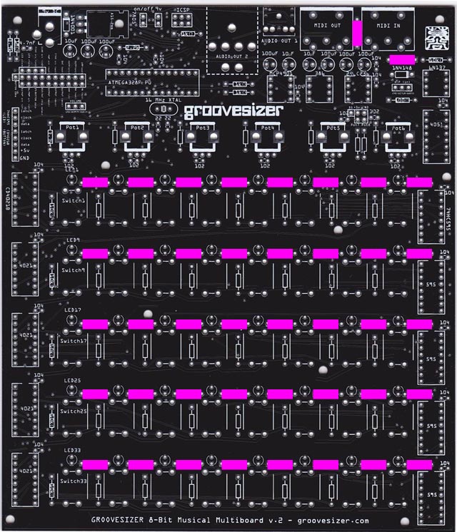
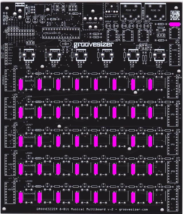
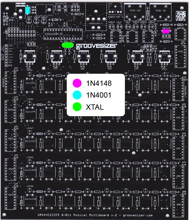
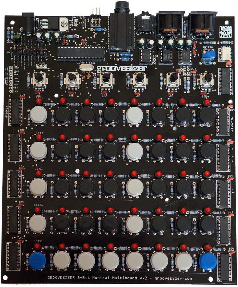
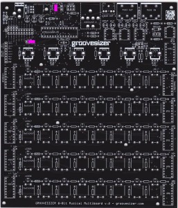
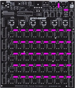
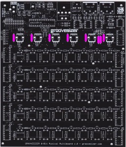
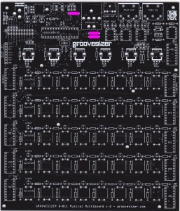
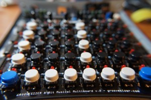
Here’s a completed board for reference (click on the images to enlarge them).
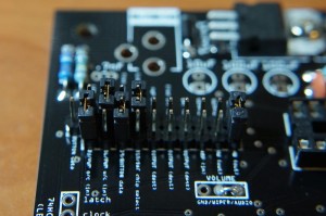
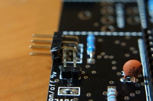
- Jumpers – we’ll start by soldering in two permanent jumpers.
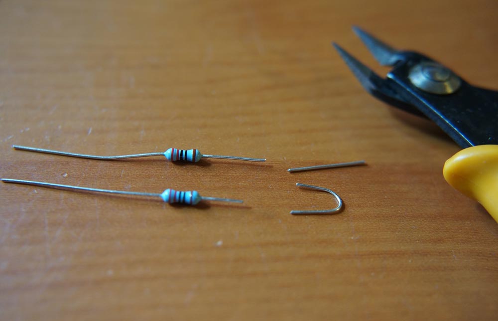
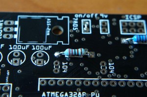
 We start here, since it’s an easy step to skip by mistake. It’s also in keeping with our plan to populate the board with components from smallest to tallest – it makes it easier to solder, since you can just flip the board around and the components will stay in place. If you have some solid core wire lying around, use that, or else snip off half (not too much now!) of the legs of some resistors – you’ll need two jumpers.
  Bend them into a staple shape and insert into the board.
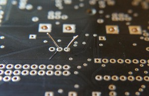
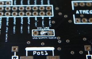
- Volume – one jumper goes between the wiper and audio pads on the volume pot header. You can skip this step if you want to add a volume pot (10k audio/logarithmic – not included). If you’re not sure whether you want a volume pot at this point, just go ahead and solder in the jumper anyway. It’s no big deal to desolder the jumper later.
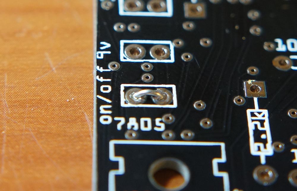
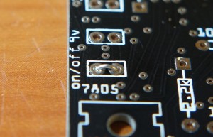
- On/Off – the other connects the on and off pads of the optional on/off switch (not included).
 Solder the jumpers and snip off the remaining legs with your cutter.
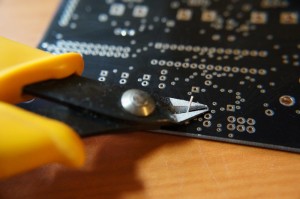 CAUTION: cutters are sharp and traces are thin, so watch out when you snip that you don’t accidentally scratch through a trace!
- Volume – one jumper goes between the wiper and audio pads on the volume pot header. You can skip this step if you want to add a volume pot (10k audio/logarithmic – not included). If you’re not sure whether you want a volume pot at this point, just go ahead and solder in the jumper anyway. It’s no big deal to desolder the jumper later.
- Resistors
- 220Ω x 42 (red, red, black, black, brown).
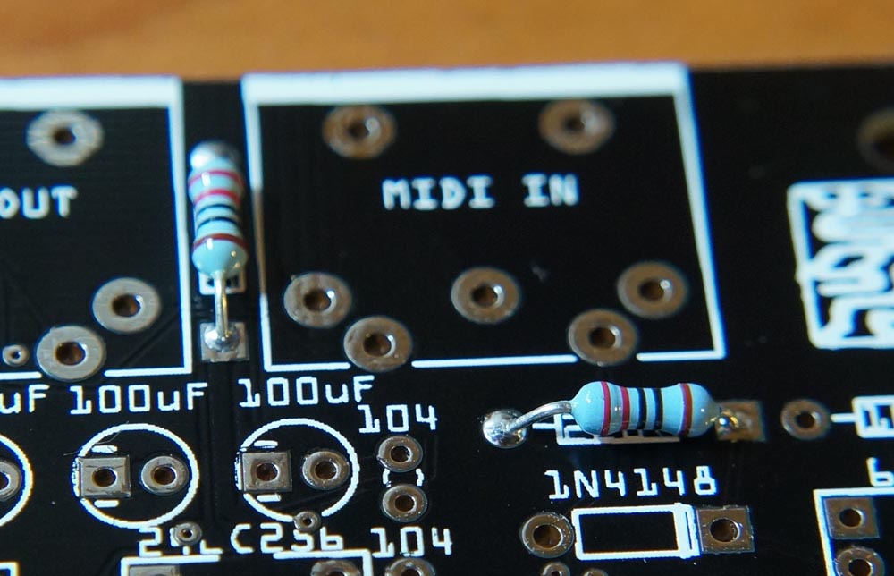
 You’ll need 1 for each LED,
 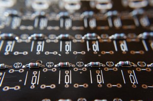 1 for the MIDI input circuit, and 1 for the MIDI ouput circuit.
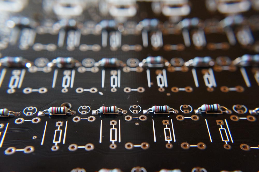
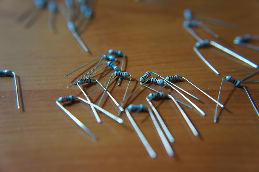
  Resistors are not polarized, so it doesn’t matter which way around they go in – that said, if you insert them all in the same orientation it’s much easier to spot a mistake. Bend the legs into a staple shape,
 and fold the legs over once you’ve inserted them into the board. You don’t need to fold them over too much – it’ll make it easier to solder and snip off the legs if you don’t.
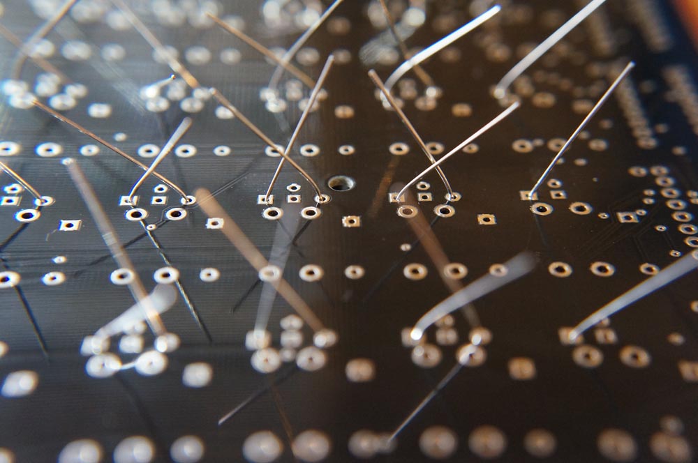
  Go ahead and solder once they’re all in, then snip off the legs.
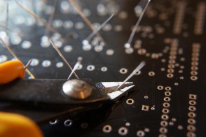
- 10kΩ x 41 (brown, black, black, red, brown).
 There’s one for each tactile switch,
 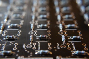 and another for the MIDI input circuit.
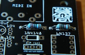 Solder and snip. You can add the remaining resistors in one go, and solder’n’snip™ when they’re all in.
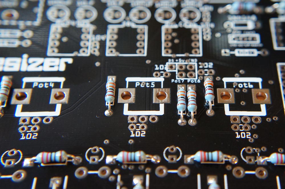
 - 3.3kΩ x 8 (orange, orange, black, brown, brown).
 You’ll add one for each potentiometer,
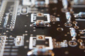 as well as for the unused analog inputs marked Pot 7 and Pot 8.
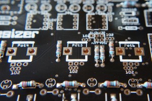
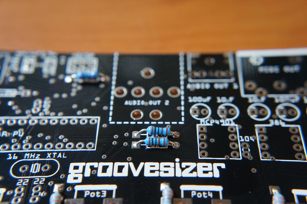
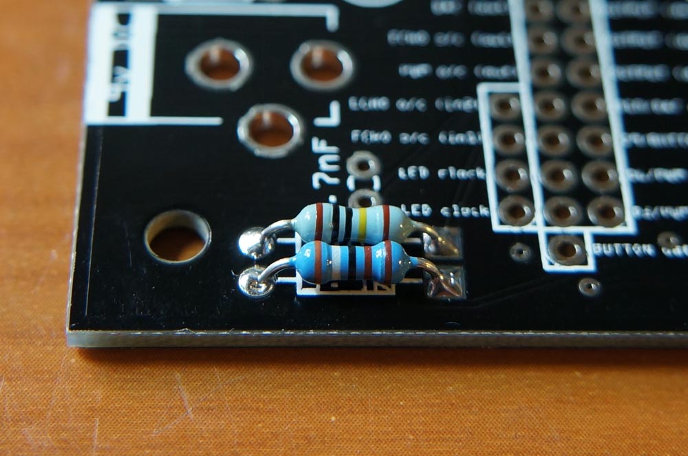
- 1kΩ x 3 (brown, black, black, brown, brown)
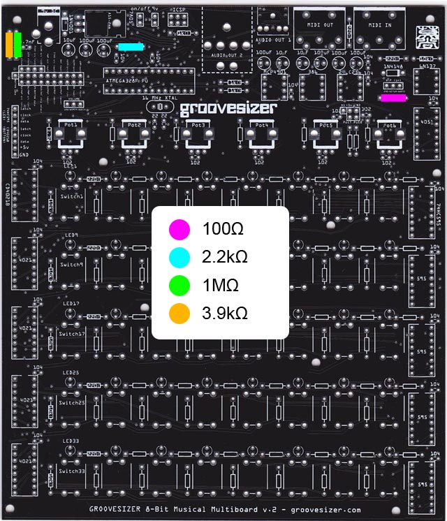
 Here’s a reference for the remaining resistors:
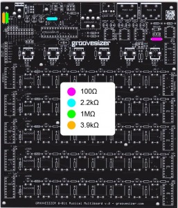
- 100Ω (brown, black, black, black, brown)
- 2.2kΩ (red, red, black, brown, brown)
- 1MΩ (brown, black, black, yellow, brown) NOTE: newer kits are shipping with a 499kΩ resistor instead (yellow, white, white, orange, brown).
- 3.9kΩ (orange, white, black, brown, brown)
 You’re done with the resistance.
- 220Ω x 42 (red, red, black, black, brown).
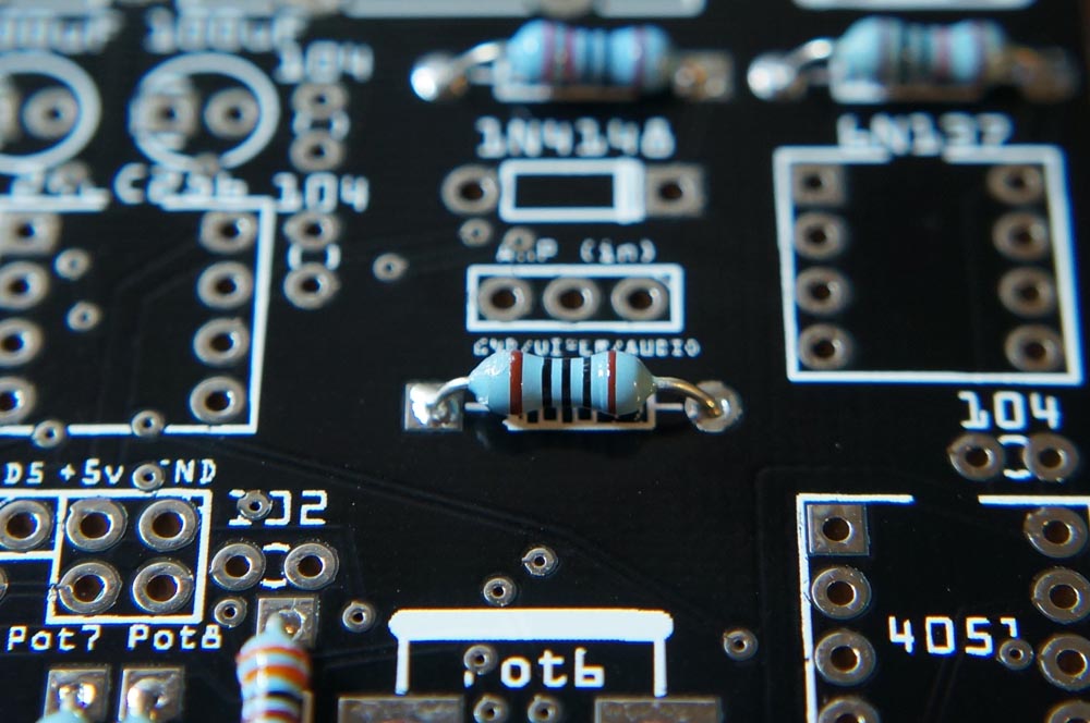
- Diodes & XTAL
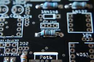
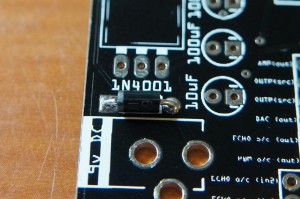
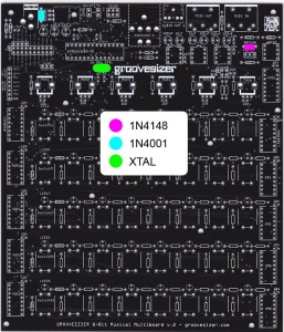 Watch out, the diodes are polarized, so pay close attention to which side the line marking on the diode body goes – it’s marked with a thicker white line on the PCB.
- 1N4148 – the 1N4148 has the see-through glass body.
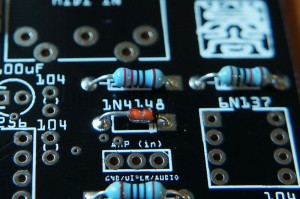
- 1N4001 – it’s the black one.
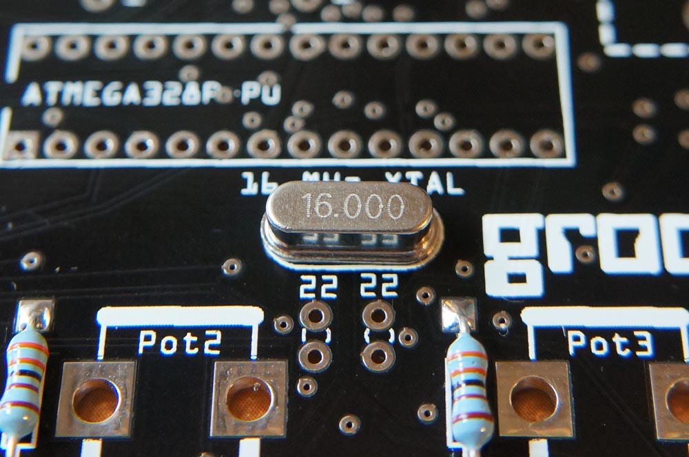
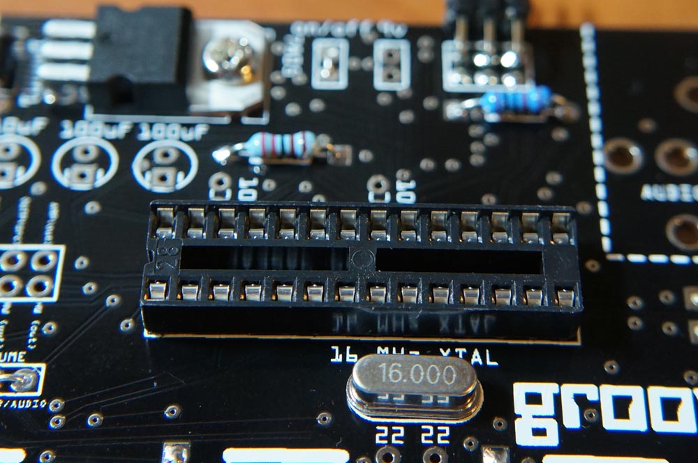
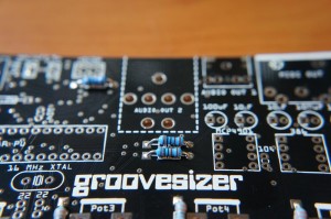
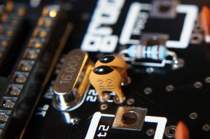
- XTAL – the crystal clock (XTAL) is not polarized, so it can go in either way.

- 1N4148 – the 1N4148 has the see-through glass body.
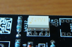
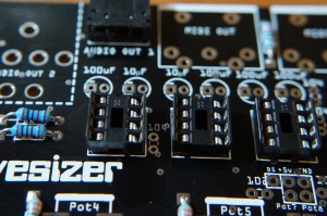
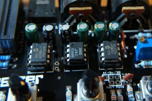
- Soldered ICs – double, nay, triple check the orientation of these. You really don’t want to get it wrong! Check with the pictures below.
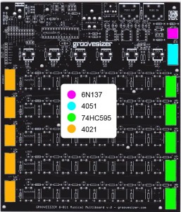
- 6N137 – an optocoupler that is used for the MIDI input circuit. The beveled edge is on the inside of the board.
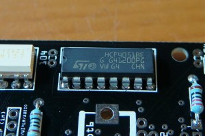
- 4051 – the multiplexer for the potentiometers. Although the Atmega 328 has 6 analog inputs, we are using two of those for the I2C protocol to communicate with the EEPROM chip. The notch goes at the top of the board (closest to the MIDI connectors).
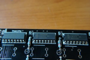
- 74HC595 x 5 – the multiplexers for the LEDs. There’s one for each row of 8 LEDs. As with the 4051, the notch goes at the top of the board.
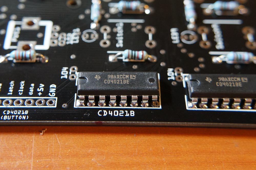
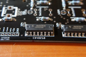
- 4021 x 5 – the multiplexers for the buttons. Again there’s one for each row of 8 buttons. The notch goes at the top of the board and the orientation of the text on the chip should be the same as on the PCB.
- 6N137 – an optocoupler that is used for the MIDI input circuit. The beveled edge is on the inside of the board.
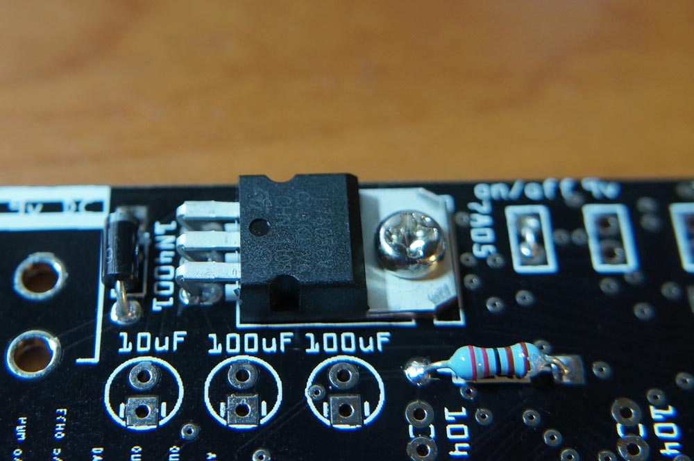
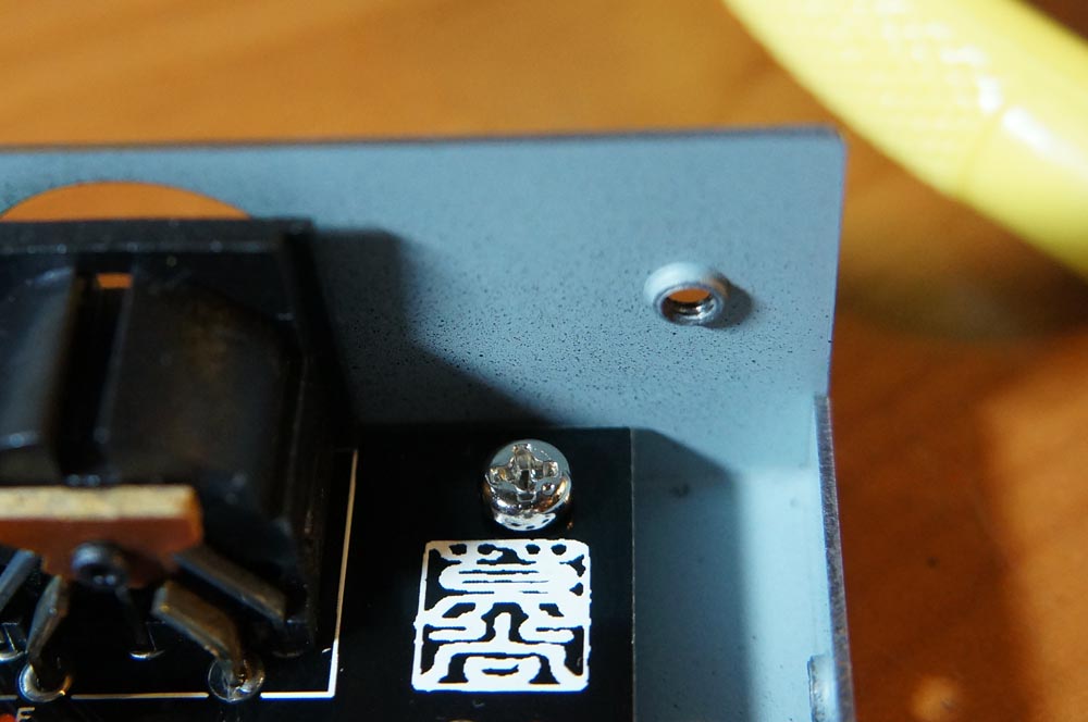
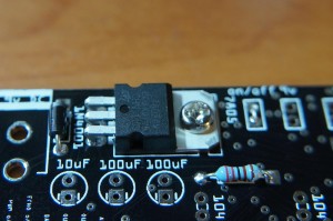
- 7805 voltage regulator – it’s polarized, but with the legs bent the way they are, there’s really only one way it can go in. Use the included screw and nut to secure the 7805 to the board. Make sure it’s flat against the board before you solder and snip.
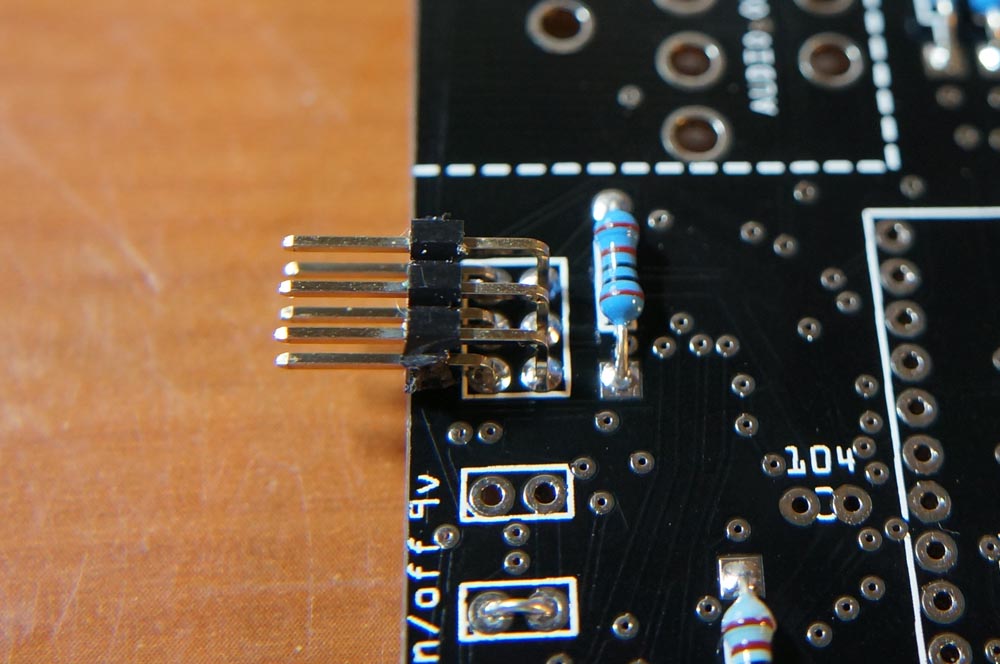
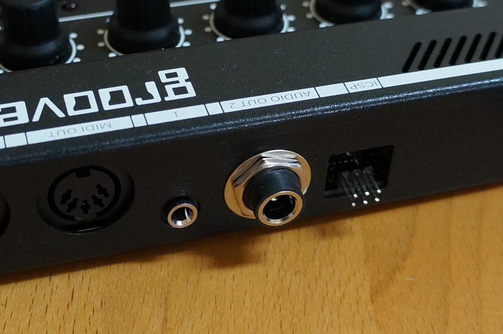
- ICSP header (90° 6 pins) – solder, but no need to snip.

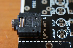
- ⅛” Mini Jack
- Dip sockets
- DIP socket (28 pins) x 1 – This is the socket for the Atmega microcontroller. The side with the notch goes on the left side of the board.

- DIP sockets (8 pins) x 3 – these are for the DAC, the amp, and the EEPROM. The notches are at the top of the board.
- DIP socket (28 pins) x 1 – This is the socket for the Atmega microcontroller. The side with the notch goes on the left side of the board.
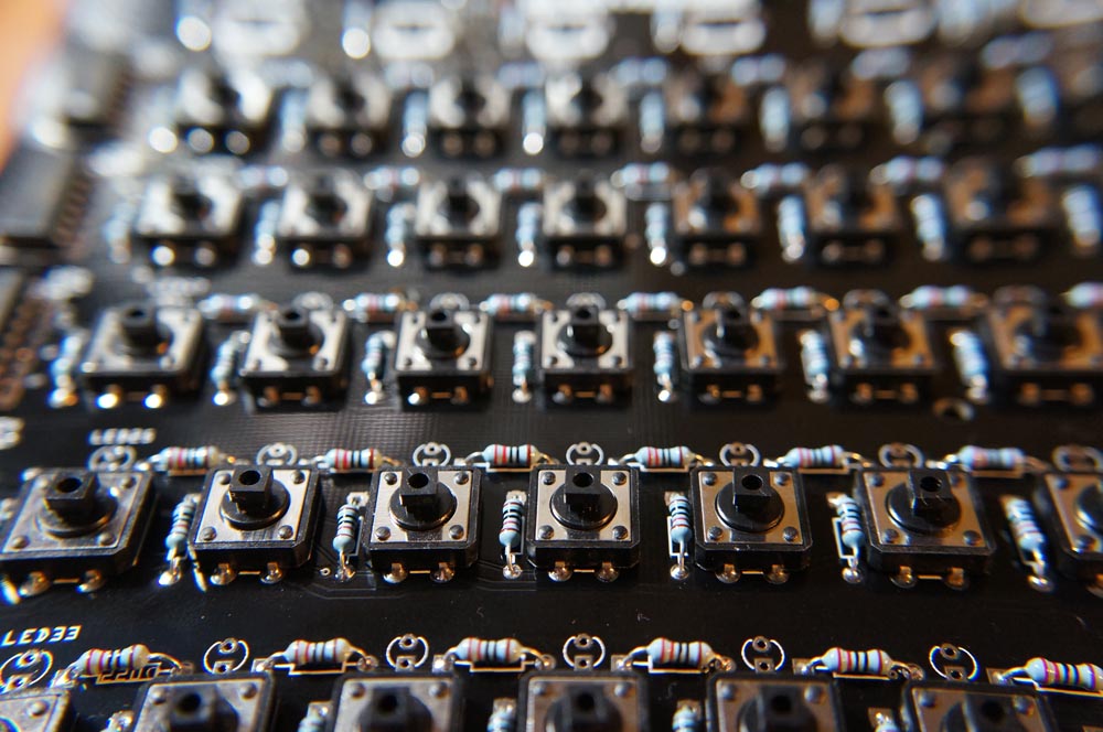
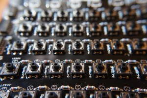
- 12mm Tactile Switches x 40 – they can go in either way, but just make sure they’re flush against the board before you solder (no snip).
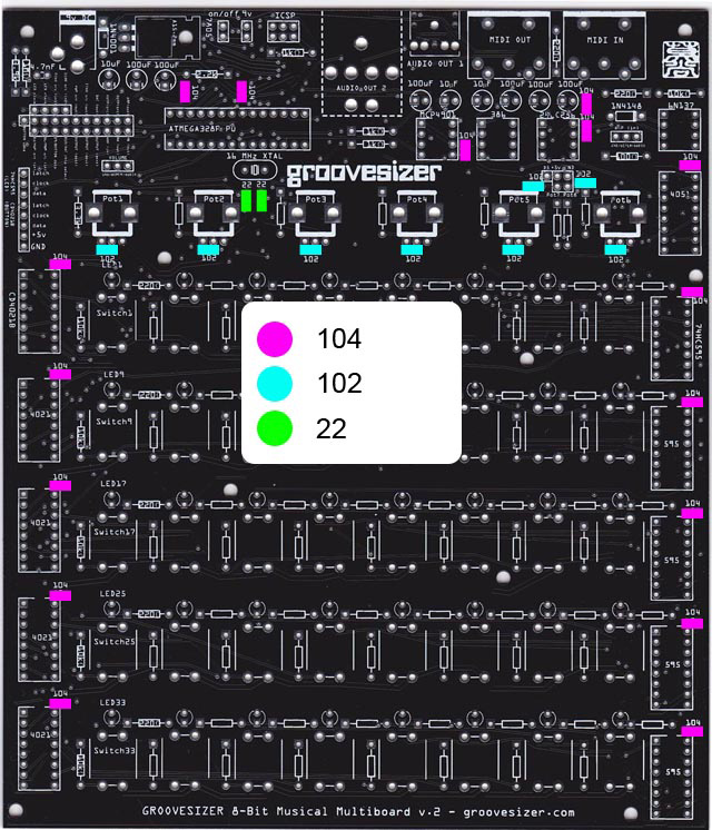
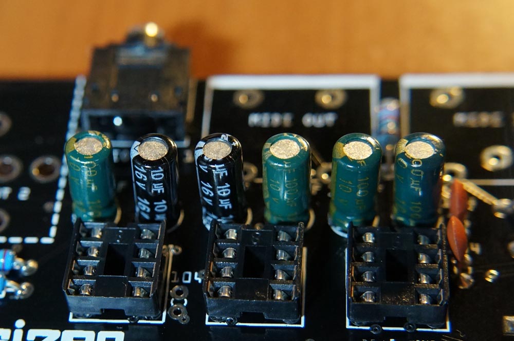
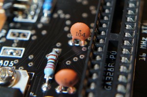
- Ceramic capacitors – these brown ceramic disks are not polarized, so they can go in either way around.
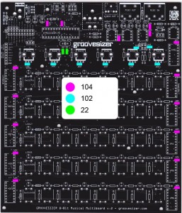
- 104 (0.10uF) capacitors x 16 – they’re marked “104”.
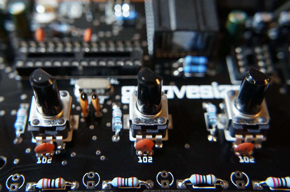
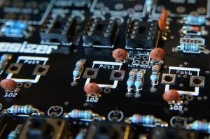
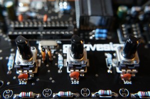
- 102 (0.001uF) capacitor x 8 – they’re marked “102”.
- 22 (22pf) x 2 – they’re marked “22” and (sometimes) have a black dot on the top rim.
- 104 (0.10uF) capacitors x 16 – they’re marked “104”.
- Jumper headers
- Options header (11 pins, 10 pins, 4 pins) – snip off the required lengths of pins from the long single row headers. Use the jumpers to anchor the single rows together and solder them to the board. To set up the jumpers for your firmware, refer to the manual of your firmware. For the Alpha firmware, see here and for the Delta, see here.
- 9V header (2 pins) – we add a header here, so we can turn off power to the 386 amp when not in use.
- Options header (11 pins, 10 pins, 4 pins) – snip off the required lengths of pins from the long single row headers. Use the jumpers to anchor the single rows together and solder them to the board. To set up the jumpers for your firmware, refer to the manual of your firmware. For the Alpha firmware, see here and for the Delta, see here.
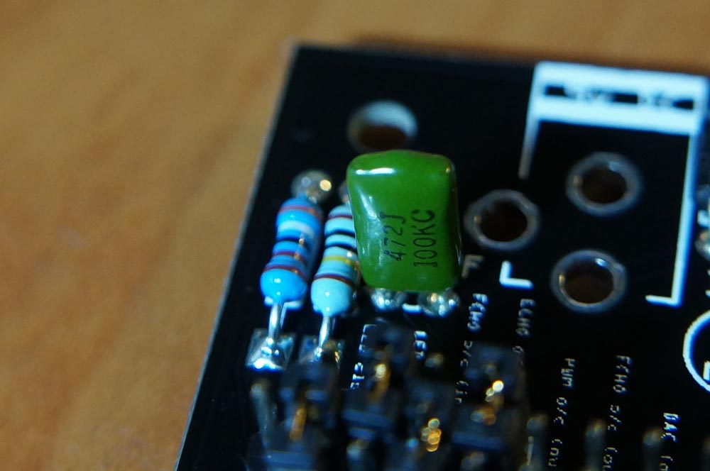
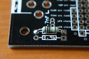
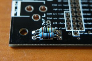
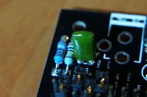
- 4.7nF capacitor x 1 (the green one – not polarized)
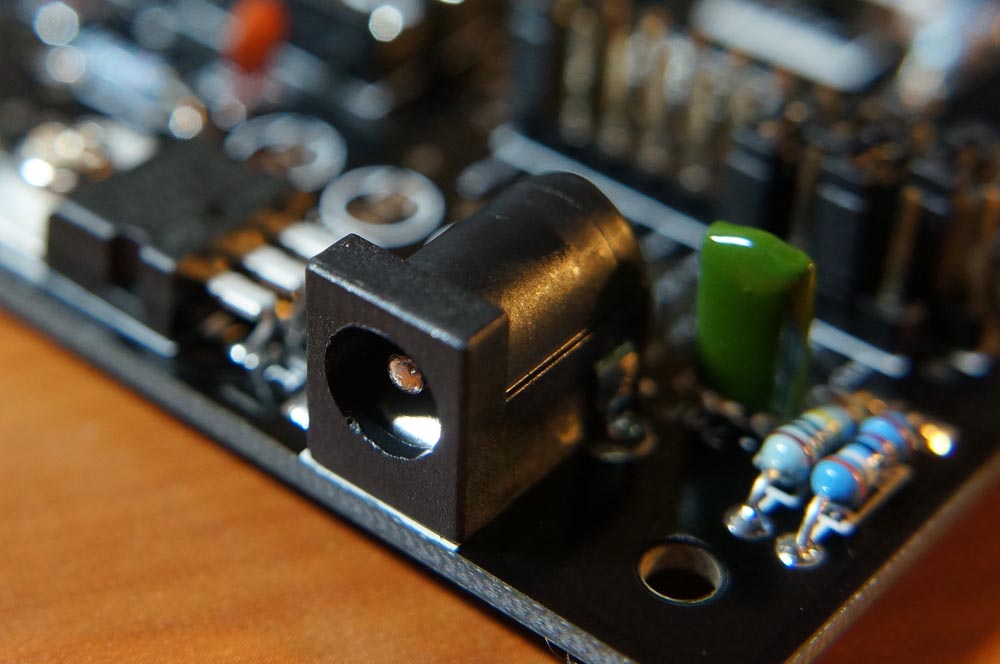
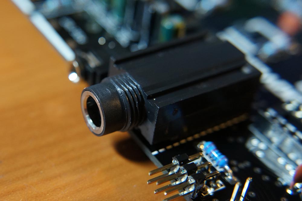
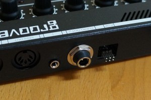
- 9v DC Power Jack – You can be generous with the solder and fill the holes, because the jack will see a lot of action and we want a solid connection to the board.

- Electrolytic capacitors – watch out – these are polarized. The white (or gold) line marked with minuses on the side of the cap indicates ground. On the board, the ground side’s pad is square and there are two white lines on either side of it.
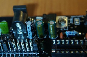

- 100uF capacitors x 6 (in the photos above they’re the green ones – they can be black too, though.)
- 10uF capacitors x 3 (the black ones in the photos)
- ¼” Jack
 Please note: Some of the parts we receive are designed with four little plastic nubs for positioning it on the PCB.
 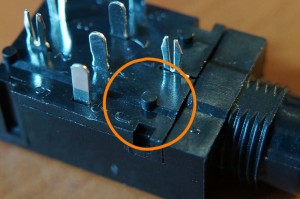 We don’t have locating holes fot them, so these need to be cut off so the jack can sit flush with the PCB and find the hole in the enclosure properly.
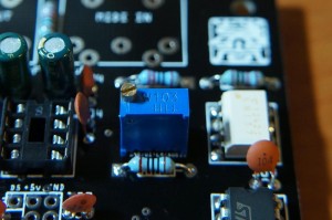
 - 10k trimmer – while it could go in either way, orient it this way with the screw on the left of the board so that turning the screw clockwise raises the input gain and turning it anticlockwise lowers the gain.
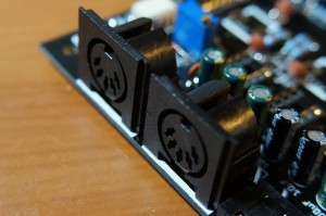
- 5 Pin DIN connectors (MIDI) x 2
- 10k Linear Potentiometers x 6 – just snap them in and solder.
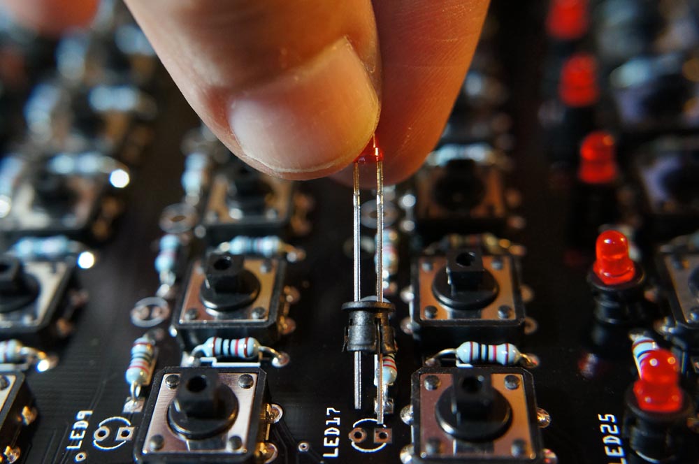
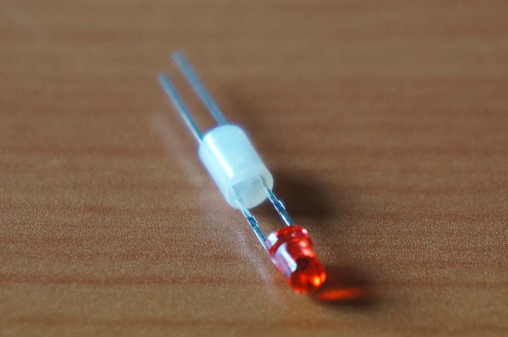
- LEDs x 40 on holders x 40. I know you’re supposed to put the LEDs in the panel-mount holders, but we’re just using them to raise the LEDs off the board. Push the legs of the LED through the holder and insert into the board. Make sure you get the orientation right! The shorter leg goes towards the top (potentiometer side) of the board. On the board, the pad for the shorter leg is round and the one for the longer leg is square.
 Later kits come with actual LED standoffs like this.
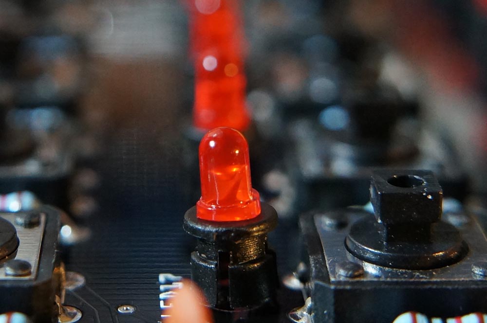
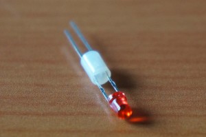 Once they’re all in and before you solder, check the orientation again. You should be able to make out a diagonal line inside the LED – make sure this line runs the same direction for all of the LEDs.
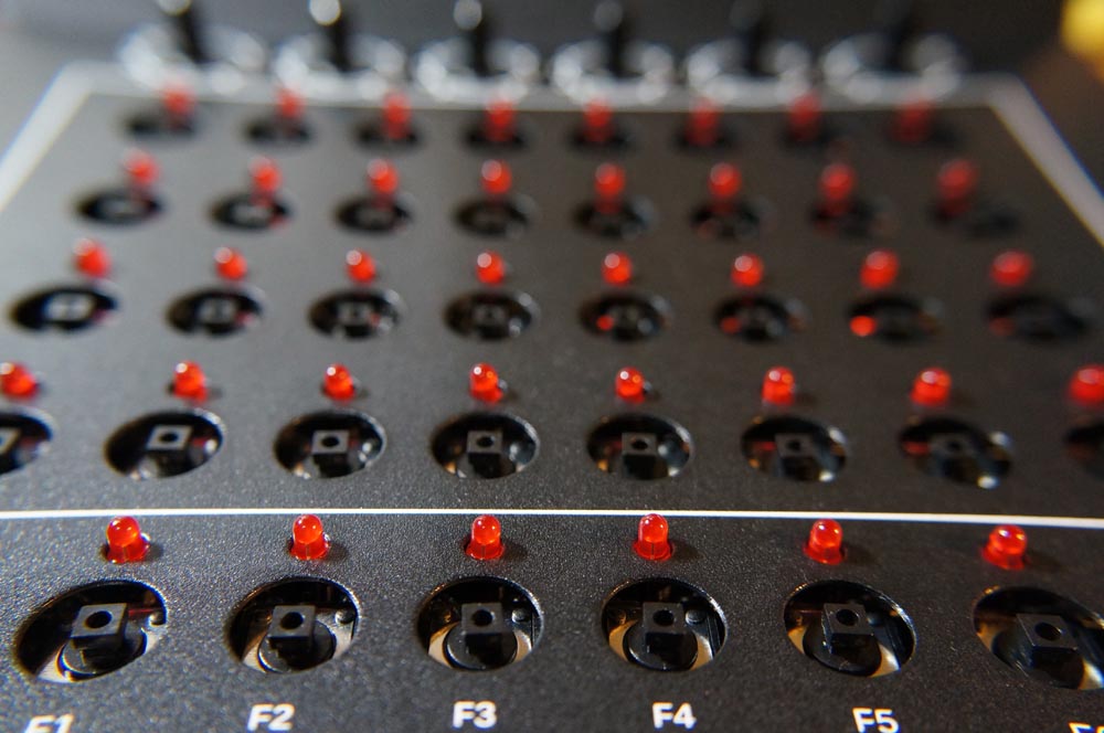
  Solder only one leg of all the LEDs first. We’re going to use the top of the enclosure as a template to make sure the LEDs are all aligned straight. You’ll probably need to bend some of the LEDs a little to make them all fit through.
 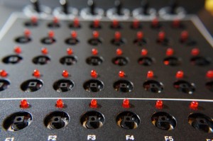 Once they’re all seated nicely in their holes, solder the other leg as well to fix the position. You can now remove the board from the top of the enclosure.
- Seat the ICs – refer to the pictures for the proper orientation.
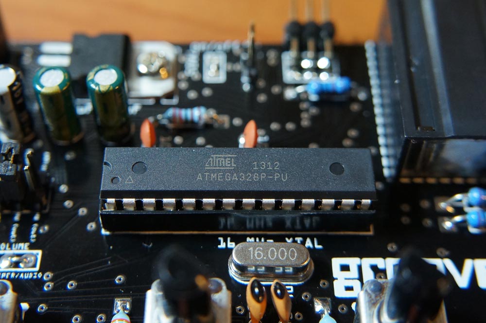
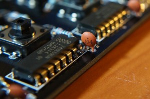
- Atmega328P-PU – the brains of the whole operation.

- MCP4901 (DAC), 386 (AMP), 24LC256 (EEPROM)
- Atmega328P-PU – the brains of the whole operation.
- Test your build! Plug a 9V DC power supply (center pin positive) into your board. They usually carry the following marking:
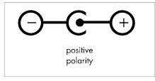 You should be greeted by a scrolling text display identifying the firmware and version. If all is not as it should be, head to the troubleshooting page for help.
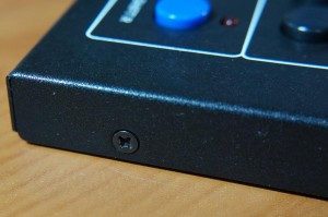
 - Fit the PCB in the enclosure bottom. Due to small variations in design for the ⅛” audio connector where some have a small section protruding beyond the edge of the board, you may need to use a little force to get the mounting holes to align properly. Start by fitting the top right mounting screw,
 and levering the board with your fingers to fit the top left screw. There are 9 mounting holes and standoffs, but securing the 4 corners is more than enough.
 - Snap on the button caps.
- Fit the enclosure top. This step should be easy since we’ve already ensured the LEDs find their proper holes.
- Do up the 10 fixing screws.
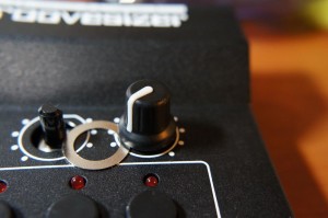
- Slide the knobs onto the potentiometer shafts. It’s possible to push the knobs so far down that they scrape against the metal of the enclosure. To prevent this, use the washer from the large audio connector as a spacer.
- Add the washer and nut to the large audio connector.
- Congratulations, you’ve done it!