If you’ve never soldered through-hole electronics before, I suggest you give yourself a quick primer with one of the numerous through-hole soldering tutorials on YouTube, like this one.
If you’ve never soldered through-hole electronics before, I suggest you give yourself a quick primer with one of the numerous through-hole soldering tutorials on YouTube, like this one.
Importantly, take all the time you need – there’s no rush. And work in a well-ventilated space.
Here’s a general tip regarding alignment of parts. First, solder only one leg of a component. Check the alignment (ie. make sure the component is straight and flush with the PCB). If it’s not, reheat the leg and realign. It’s almost impossible to do this kind of alignment once more than one leg is soldered.
PCB VERSION
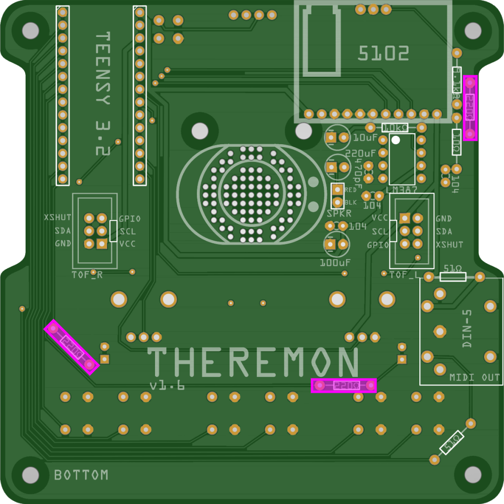
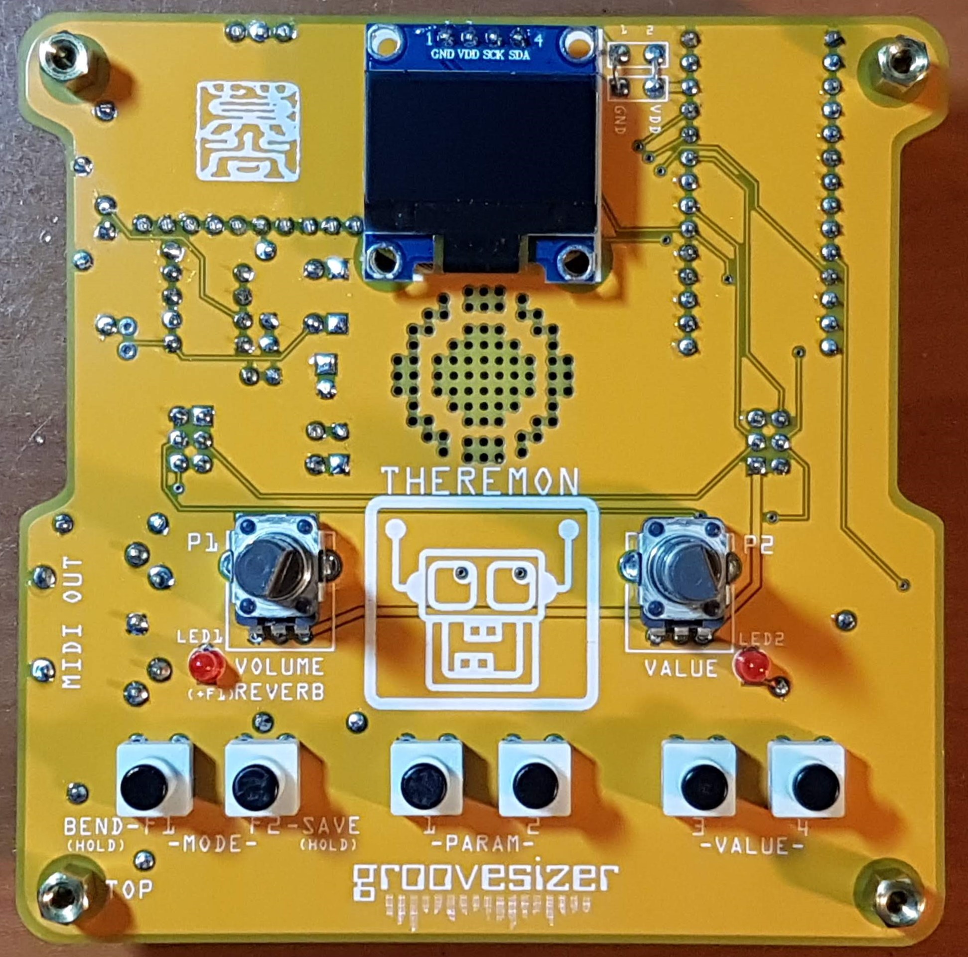
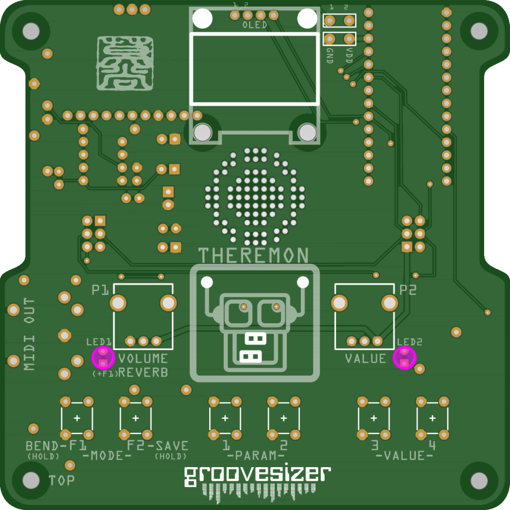
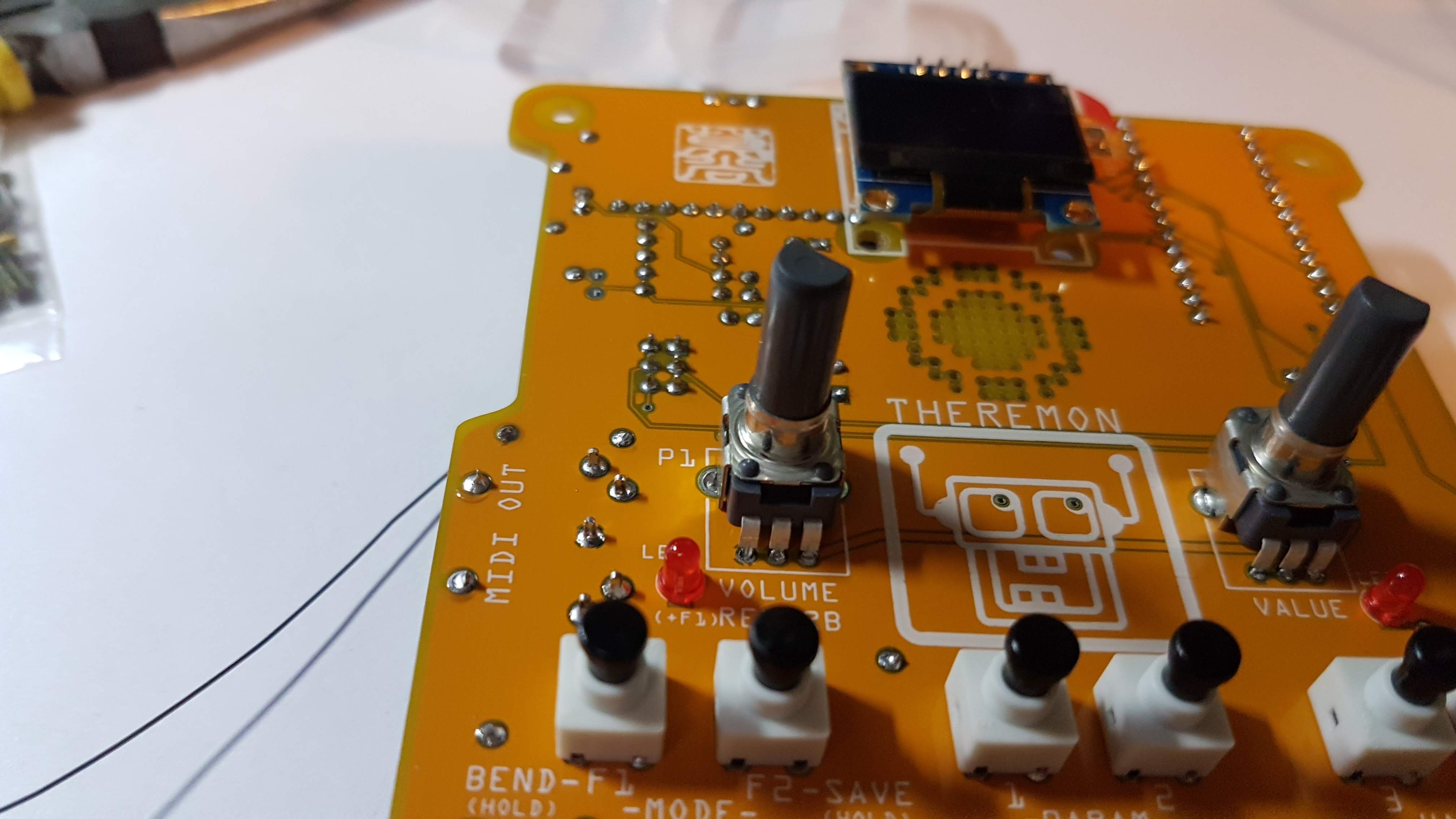
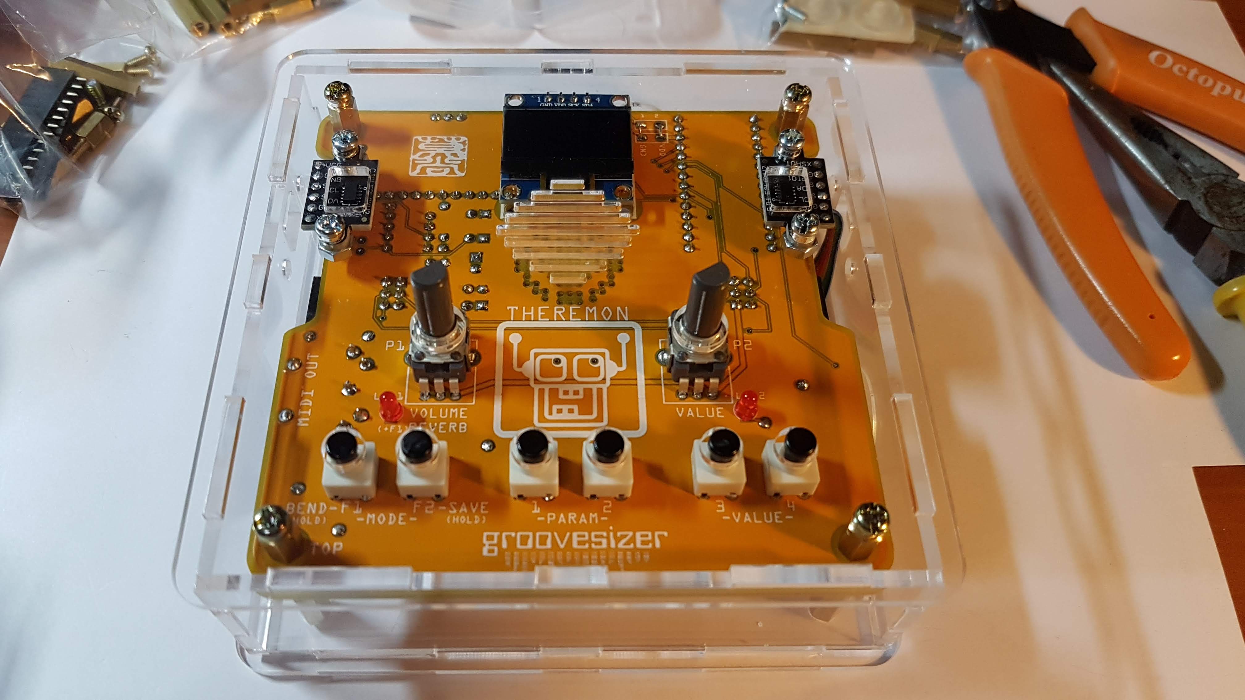
These instructions are for the V2 version of the PCB that has straight sides.
V2 PCB
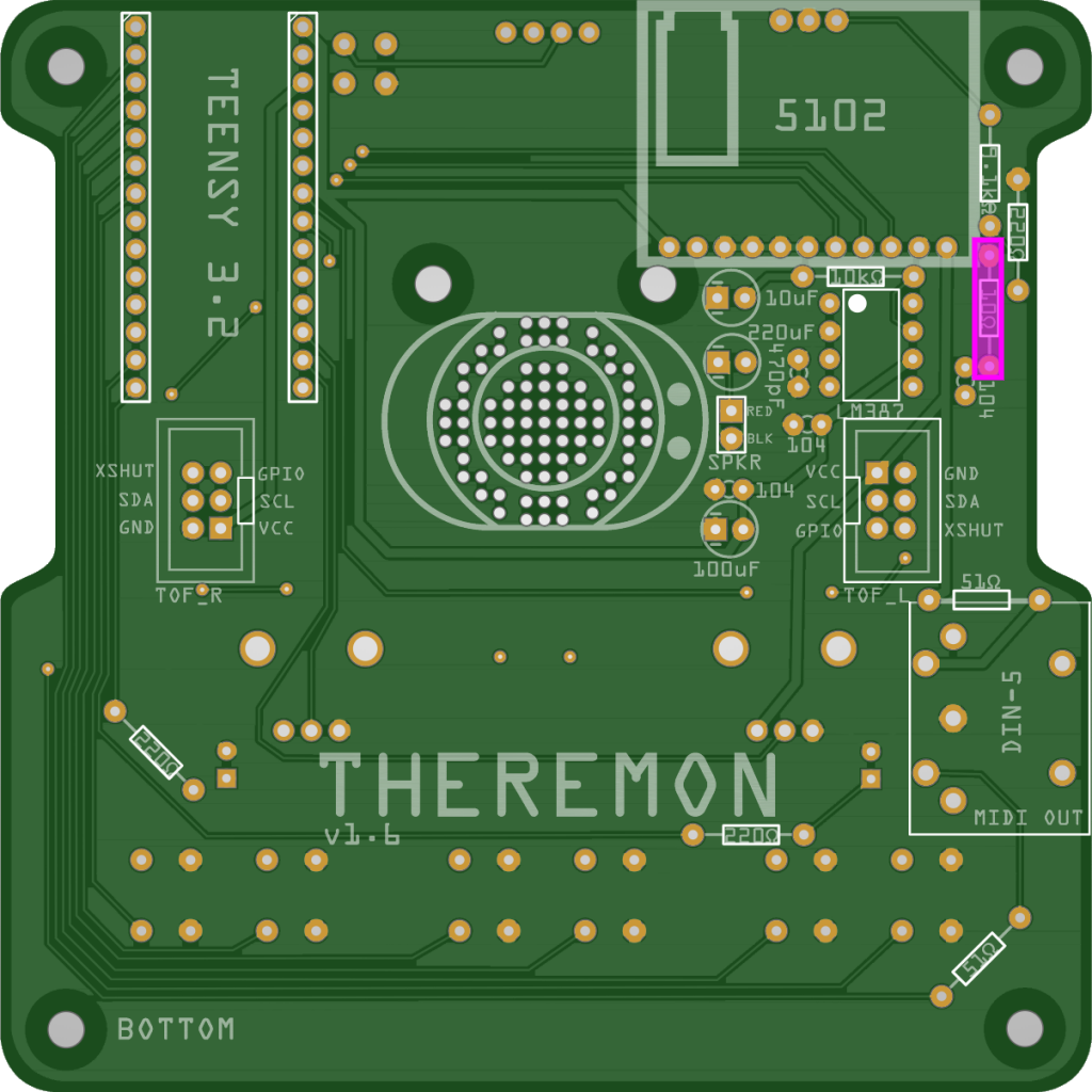
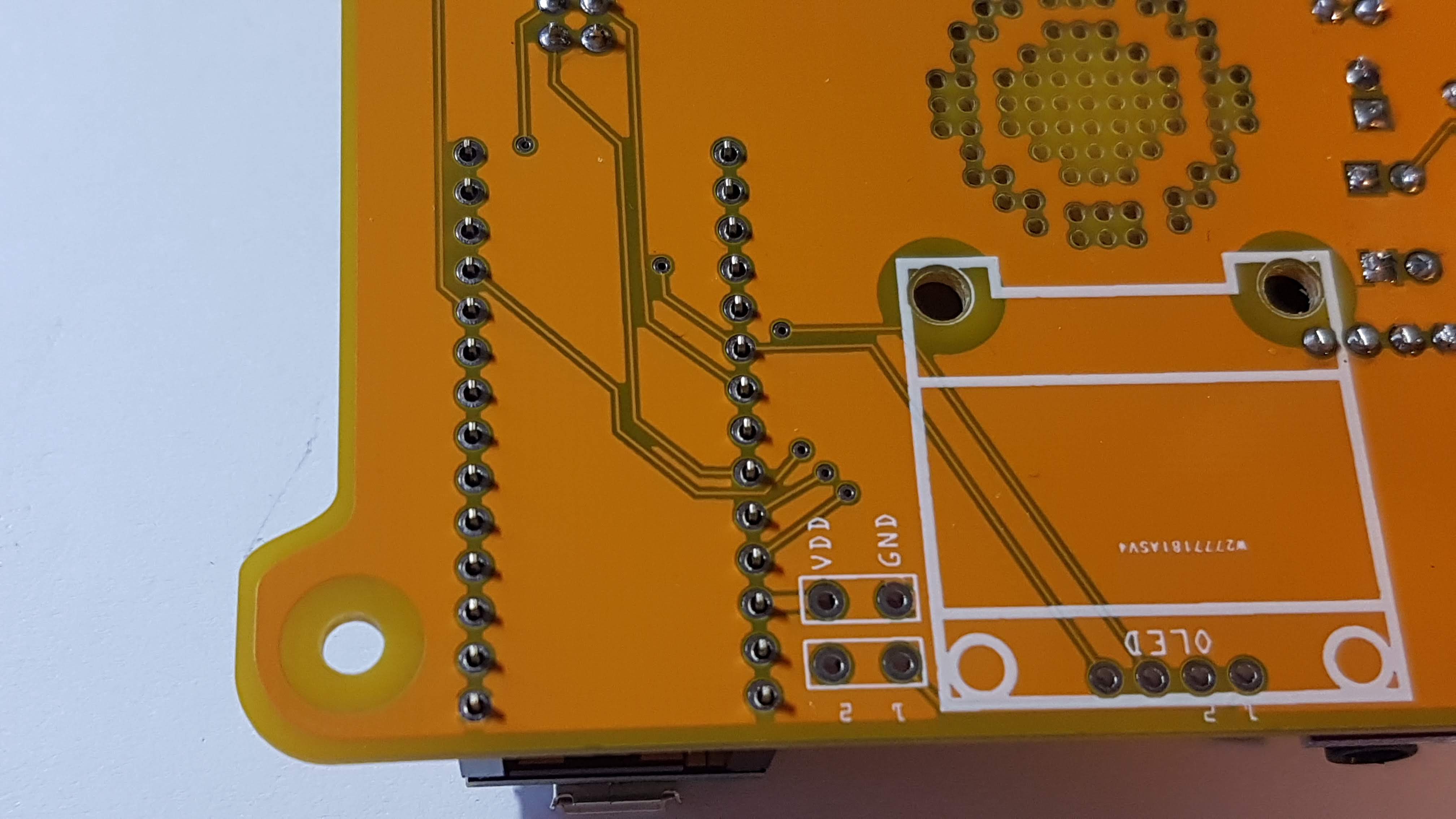
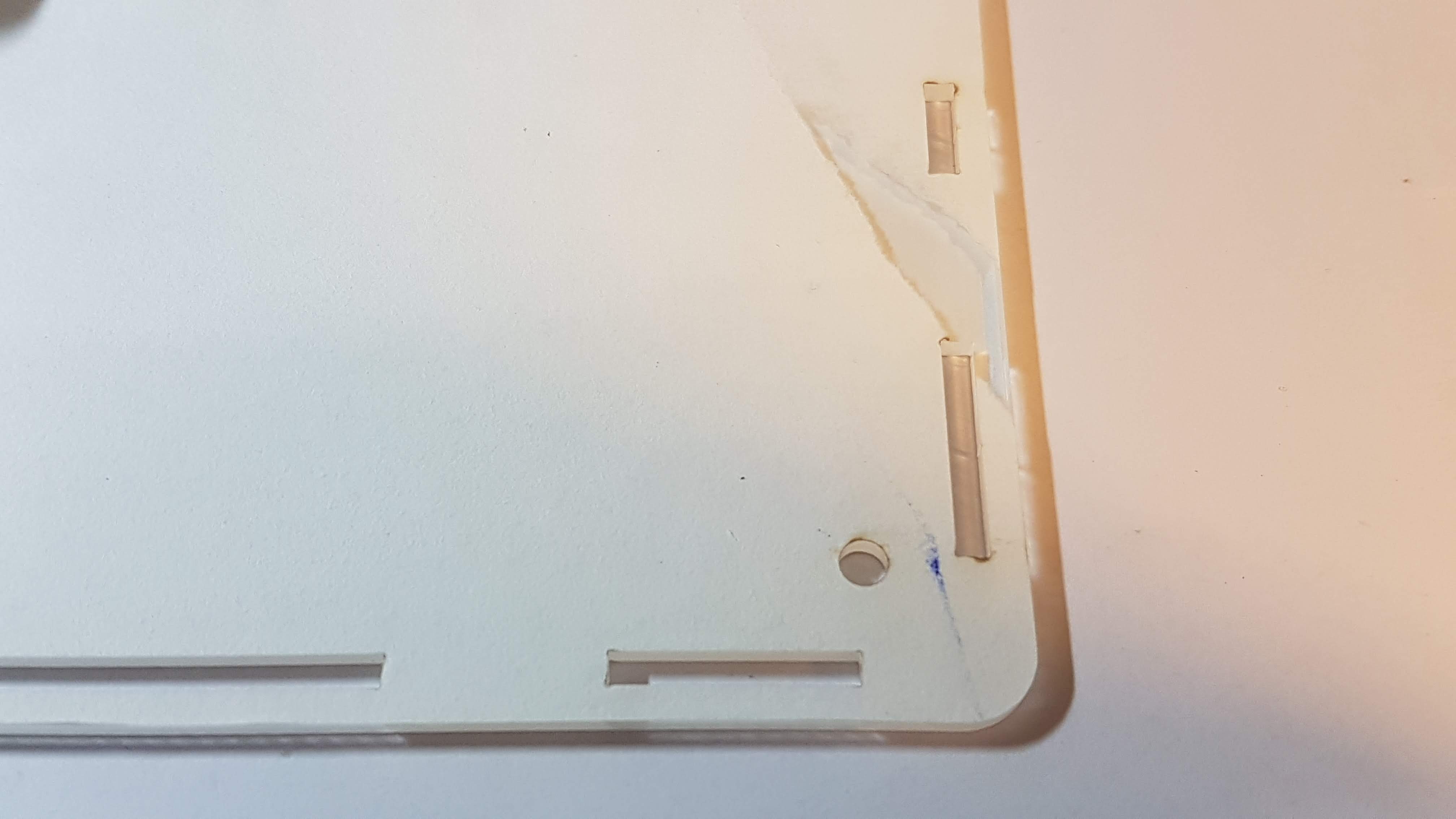
If your board has indentations on the sides as in the image below, you’ll want to use the V1 instructions instead.
V1 PCB
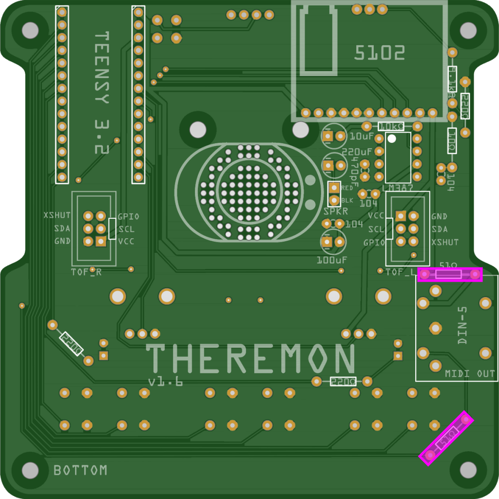
PCB BOTTOM
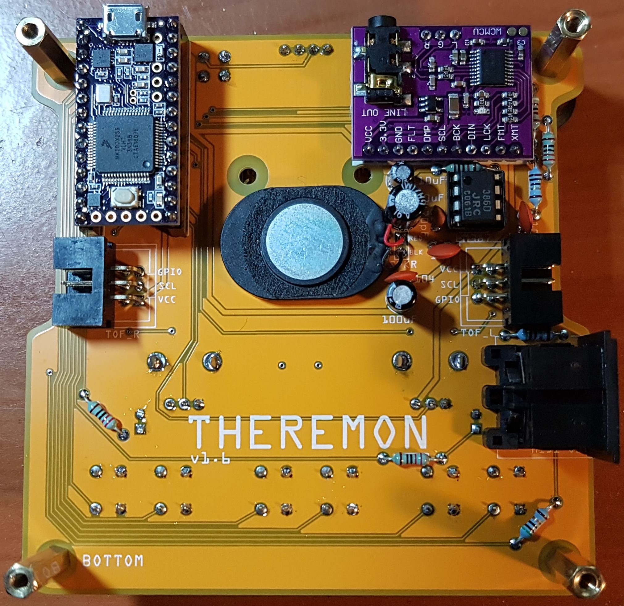
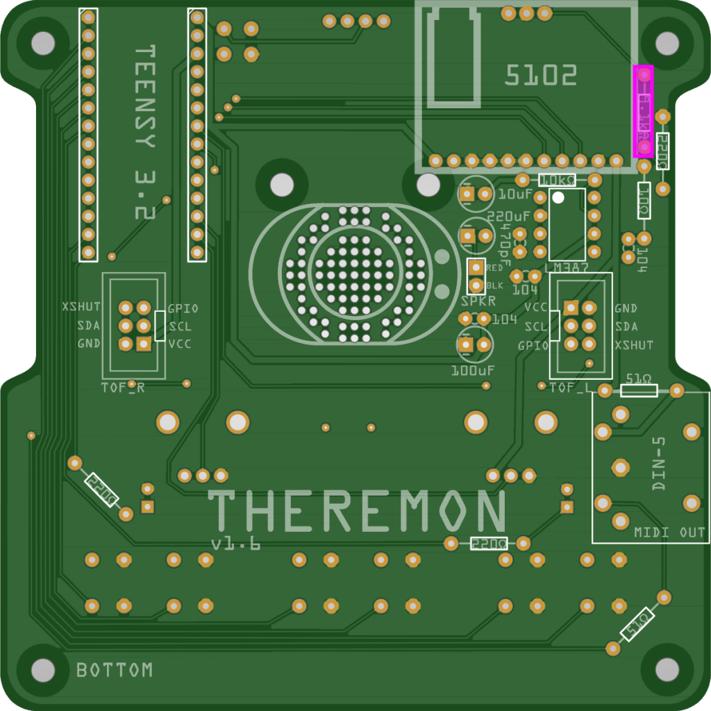
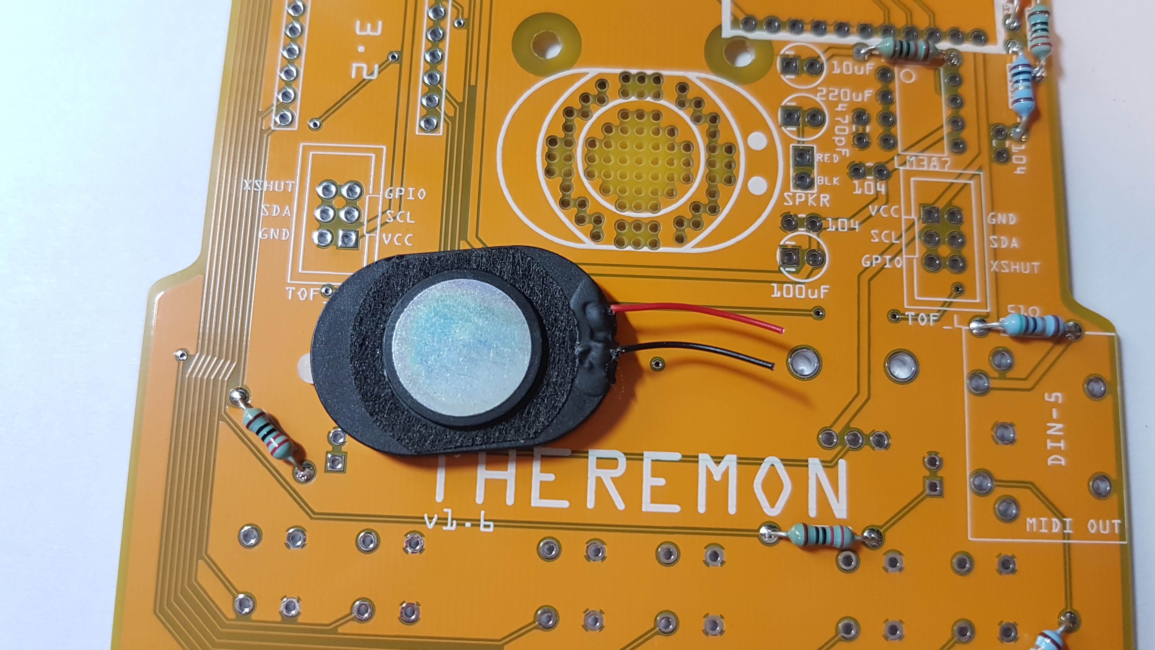
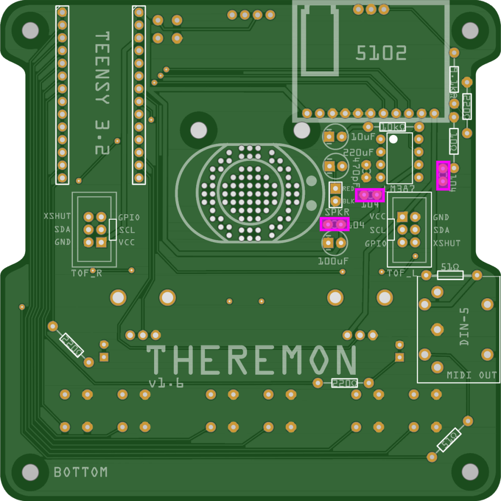
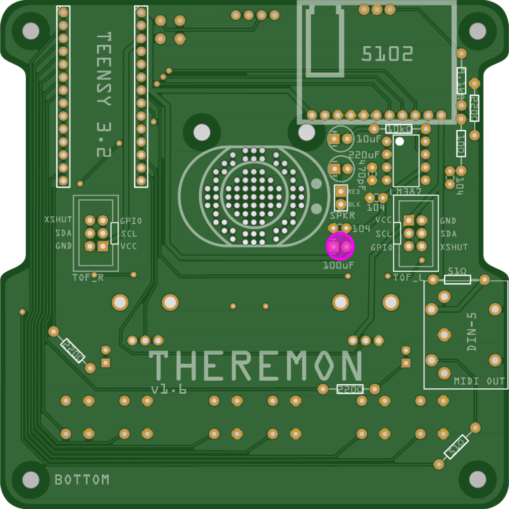
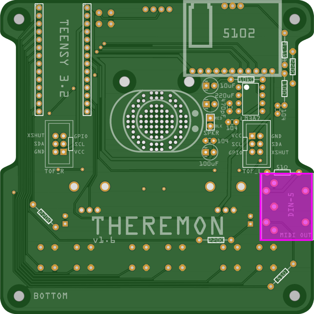
We’ll populate the bottom of the board first (BOTTOM is silkscreened in the bottom left corner). Here’s a shot of the completed bottom of the board for reference (click on any of the images to enlarge them.)
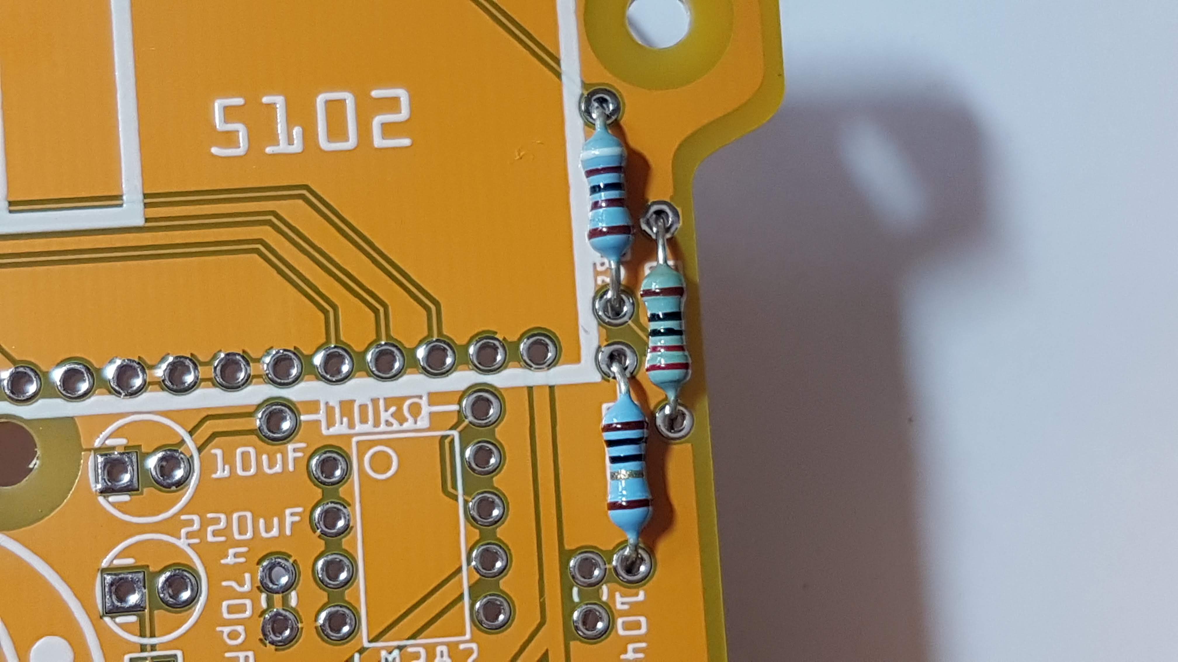
1. Resistors
We can populate all of the resistors, then solder them all in one go. They are not polarized, so it doesn’t matter which way around they go in.
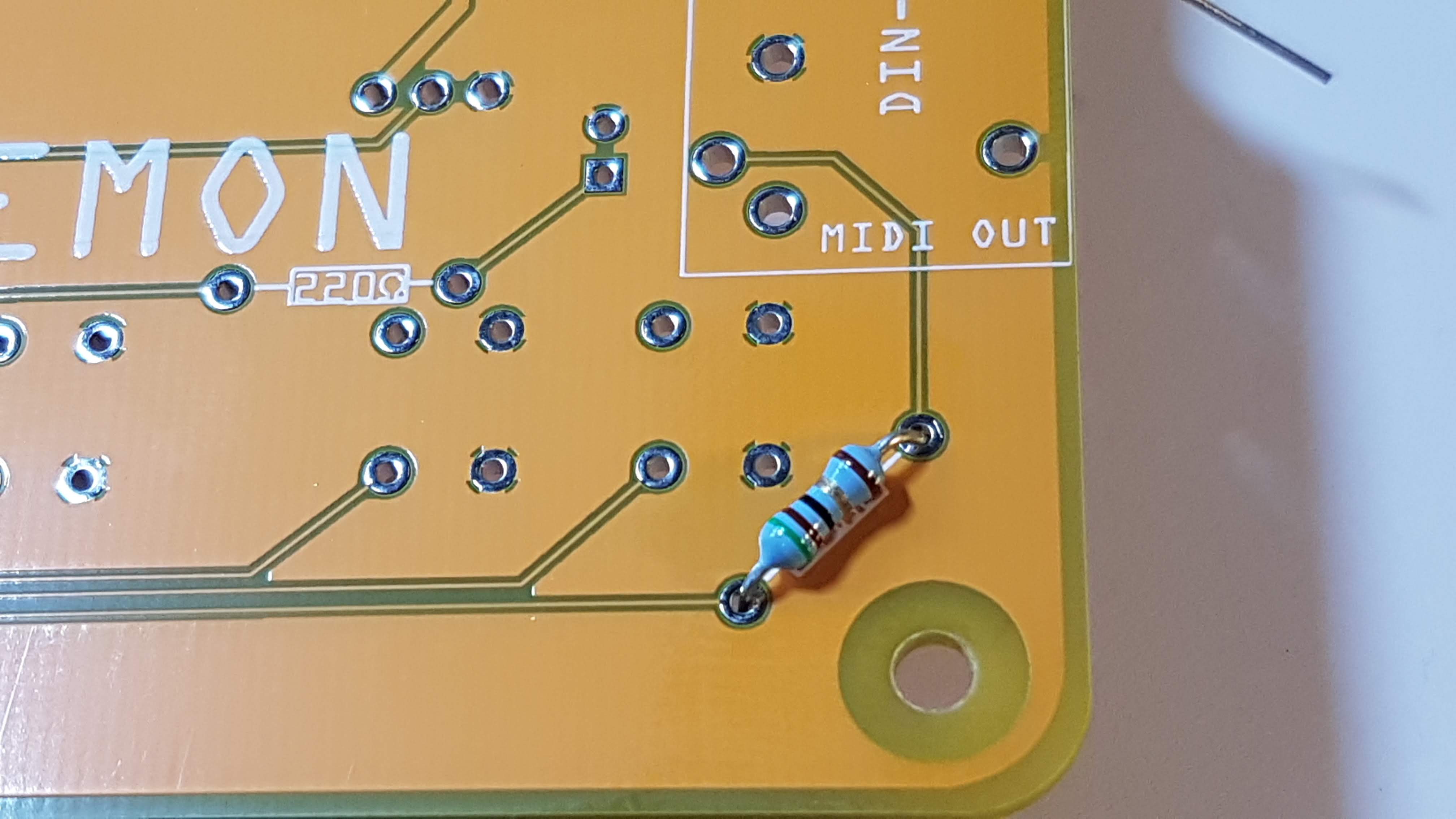
1.1 51Ω x 2 (Green, brown, black, gold, brown)
These resistors are required by the MIDI output on the DIN connector.
Bend the resistors legs into a U shape, and insert on the bottom side of the PCB.
On the top side, bend the legs – not by too much, but just enough so that the resistors don’t fall out when you flip the board over to solder.
1.2 220Ω x 3 (Red, red, black, black, brown)
The two resistors at the bottom are current limiting resistors for the two LEDs. The other is part of the LM386 amplifier circuit, along with all the other resistors and caps we’ll be adding.
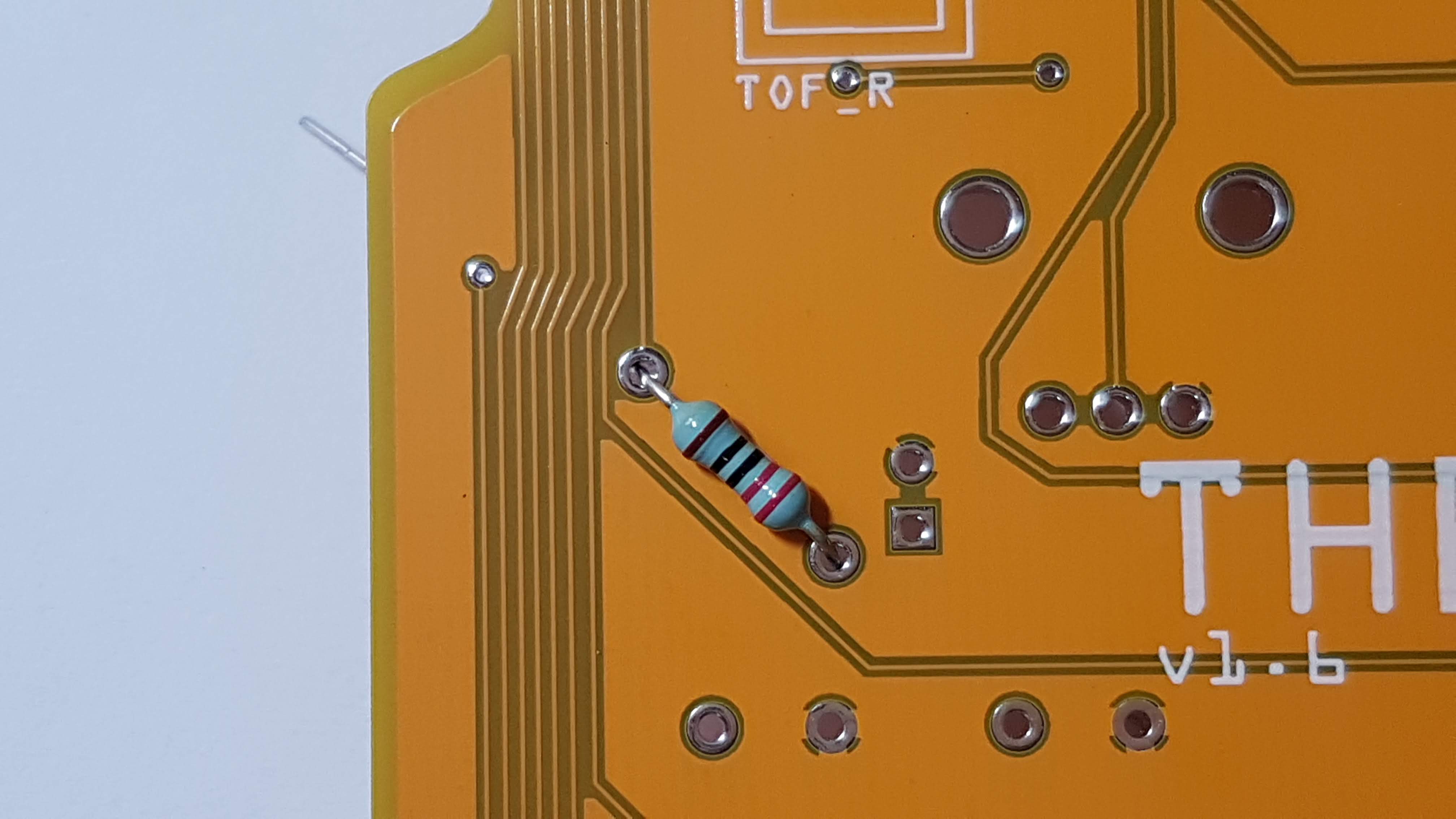
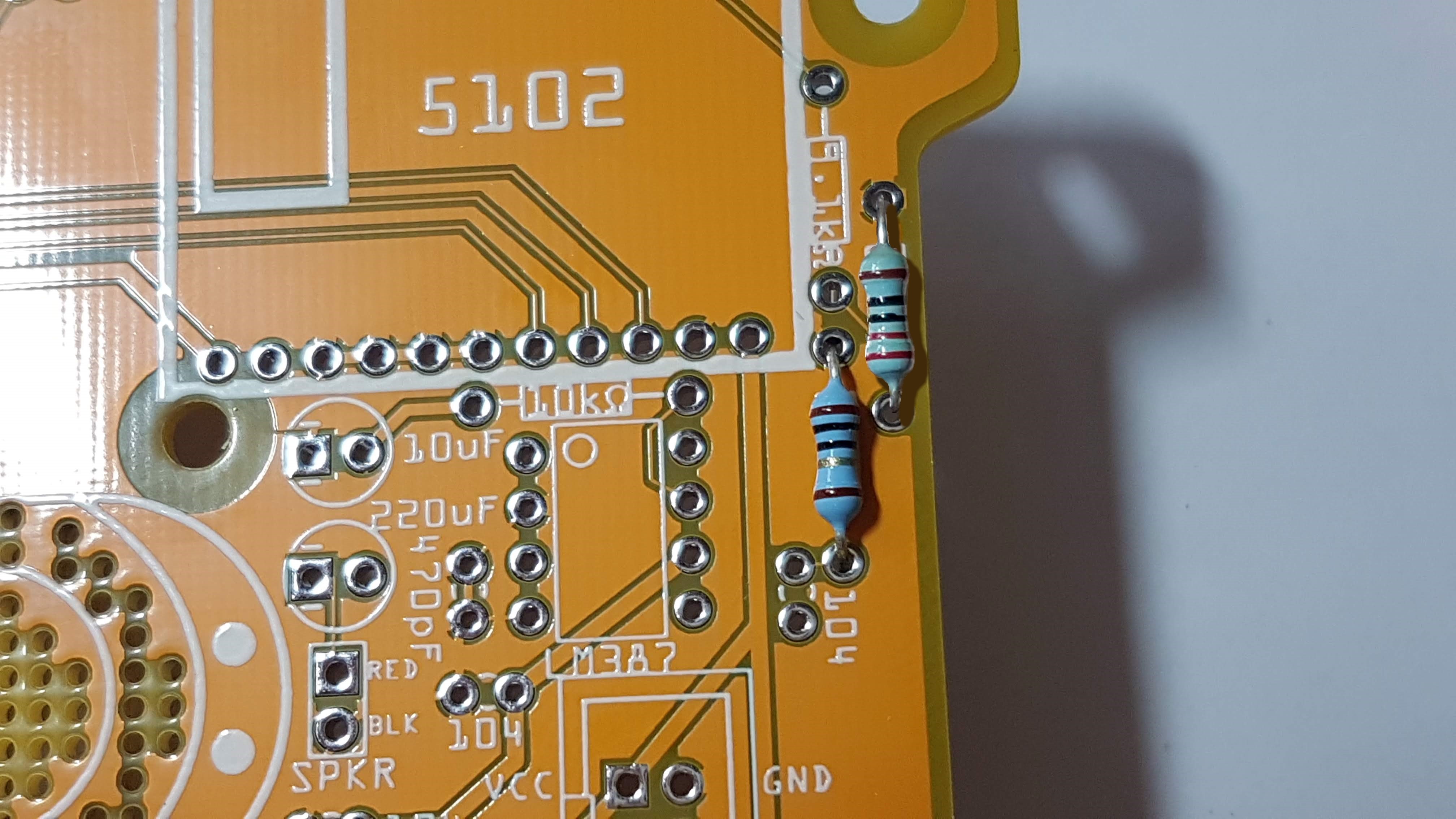
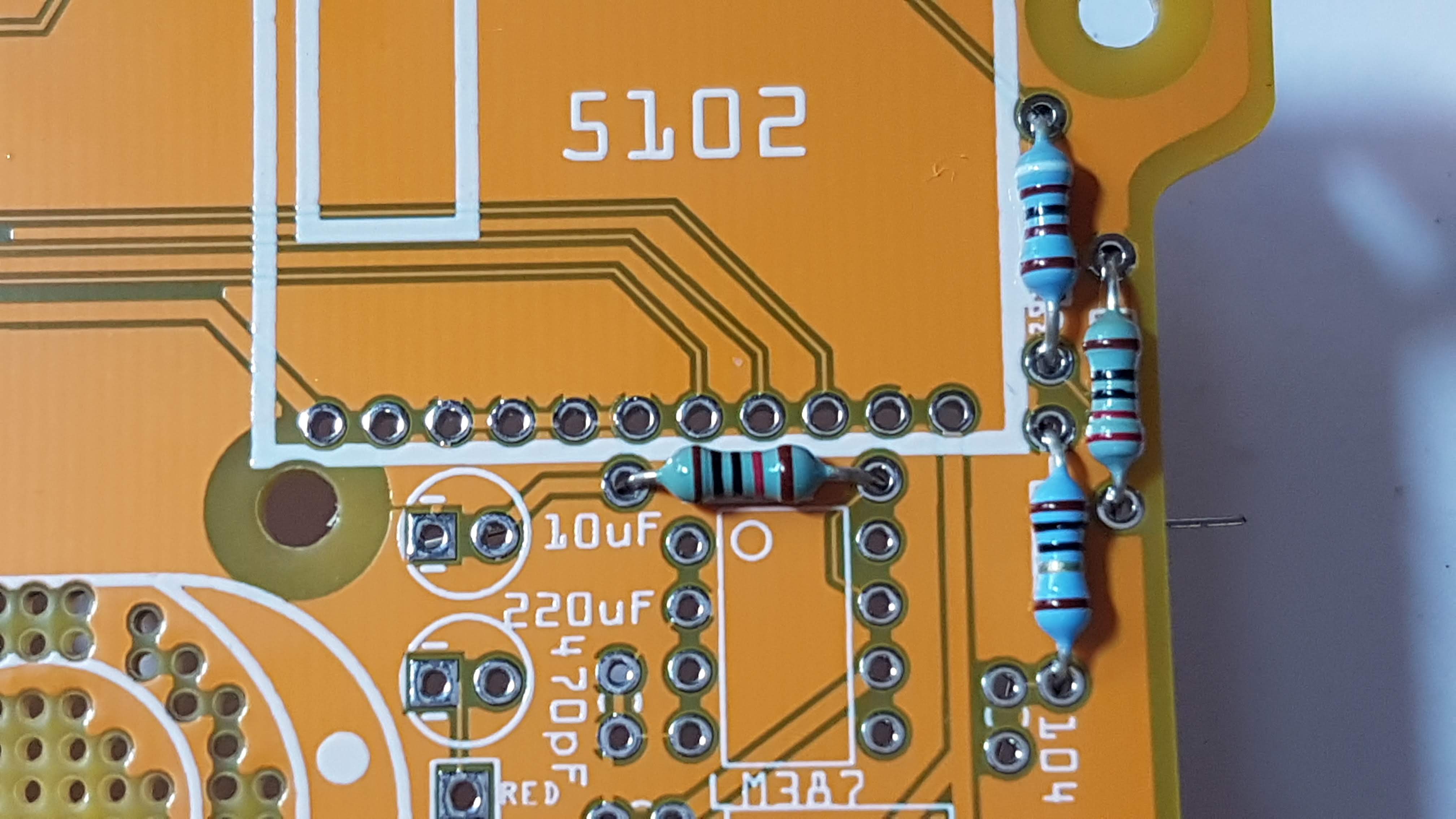
1.3 10Ω (Brown, black, black, gold, brown)
1.4 9.1kΩ (White, brown, black, brown, brown)
1.5 10kΩ (Brown, black, black, red, brown)
Time to flip the board over, solder all the legs, then use your edge cutters to snip the legs off.
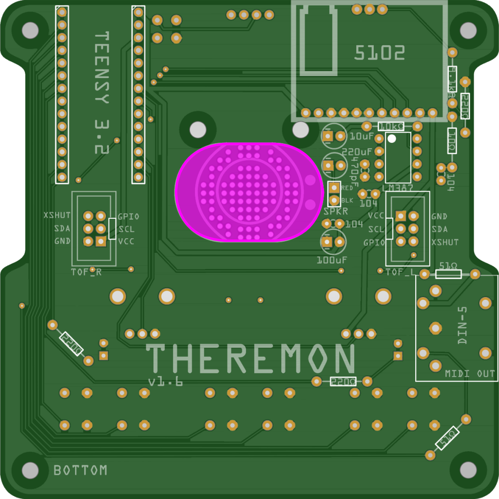
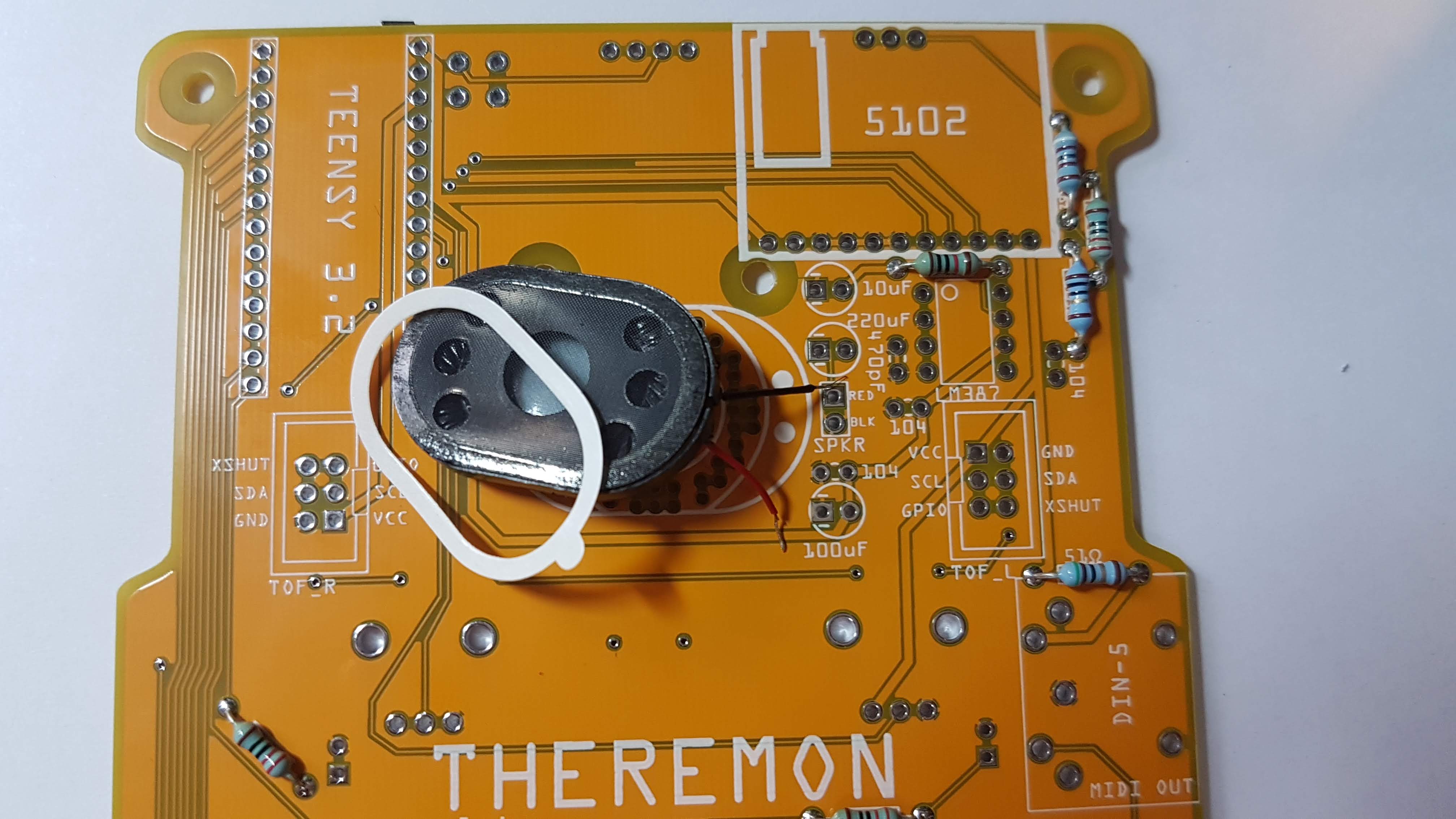
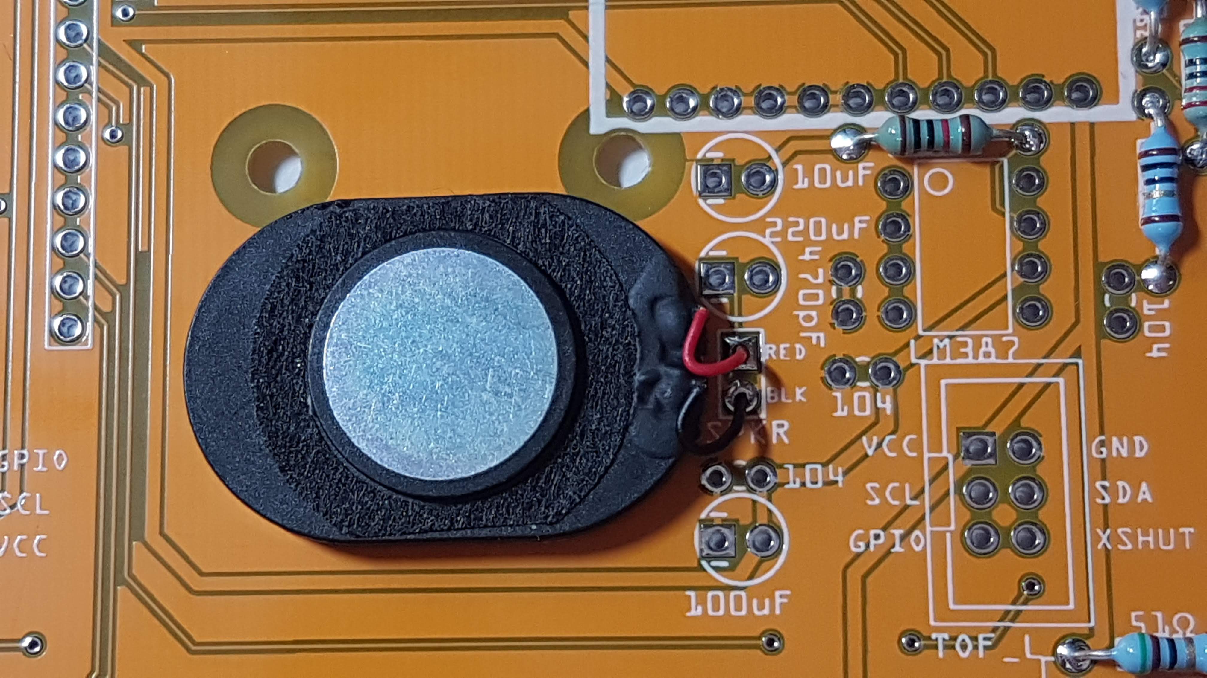
2. 8 Ω Speaker
We’ll need to trim the leads on the speaker. Not too short, mind you – the copper wire is thin and can break easily when you strip off the plastic sheathing. Leave some room for mistakes.
Remove the backing from the sticky bottom rim of the speaker.
Stick the speaker down on the white outline, then solder the corresponding leads to the pads marked RED and BLK.
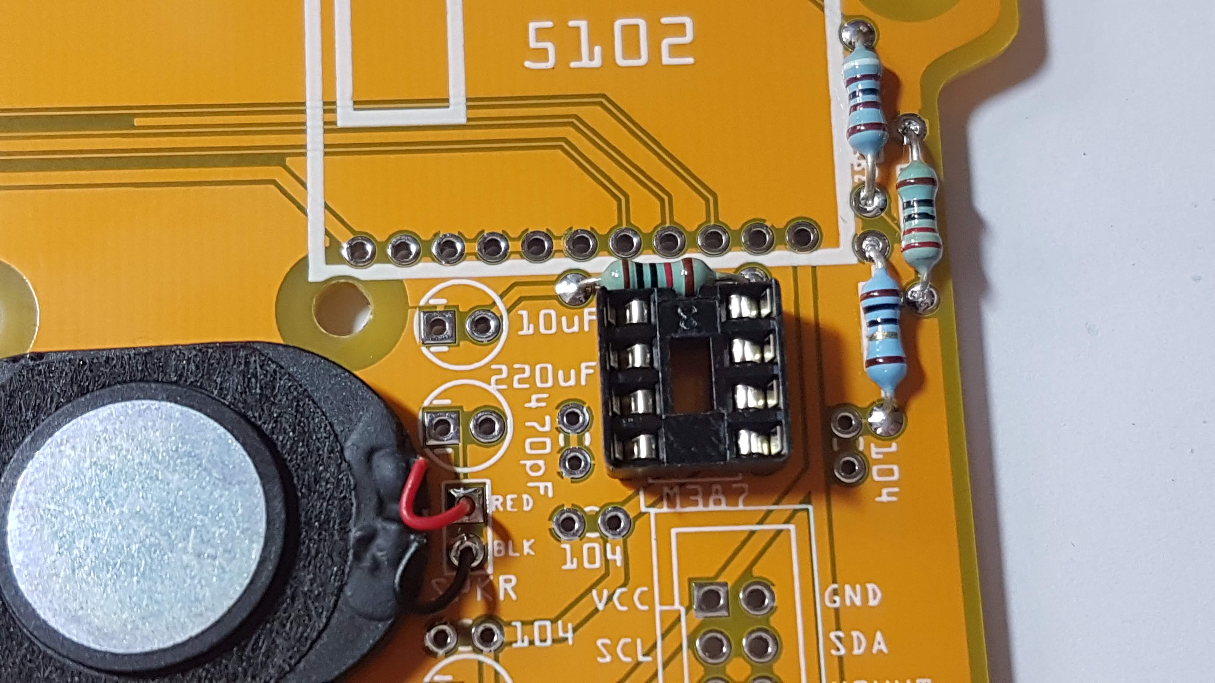
3. 8-Pin Dip Socket
The dip socket will hold the LM386 amp IC.
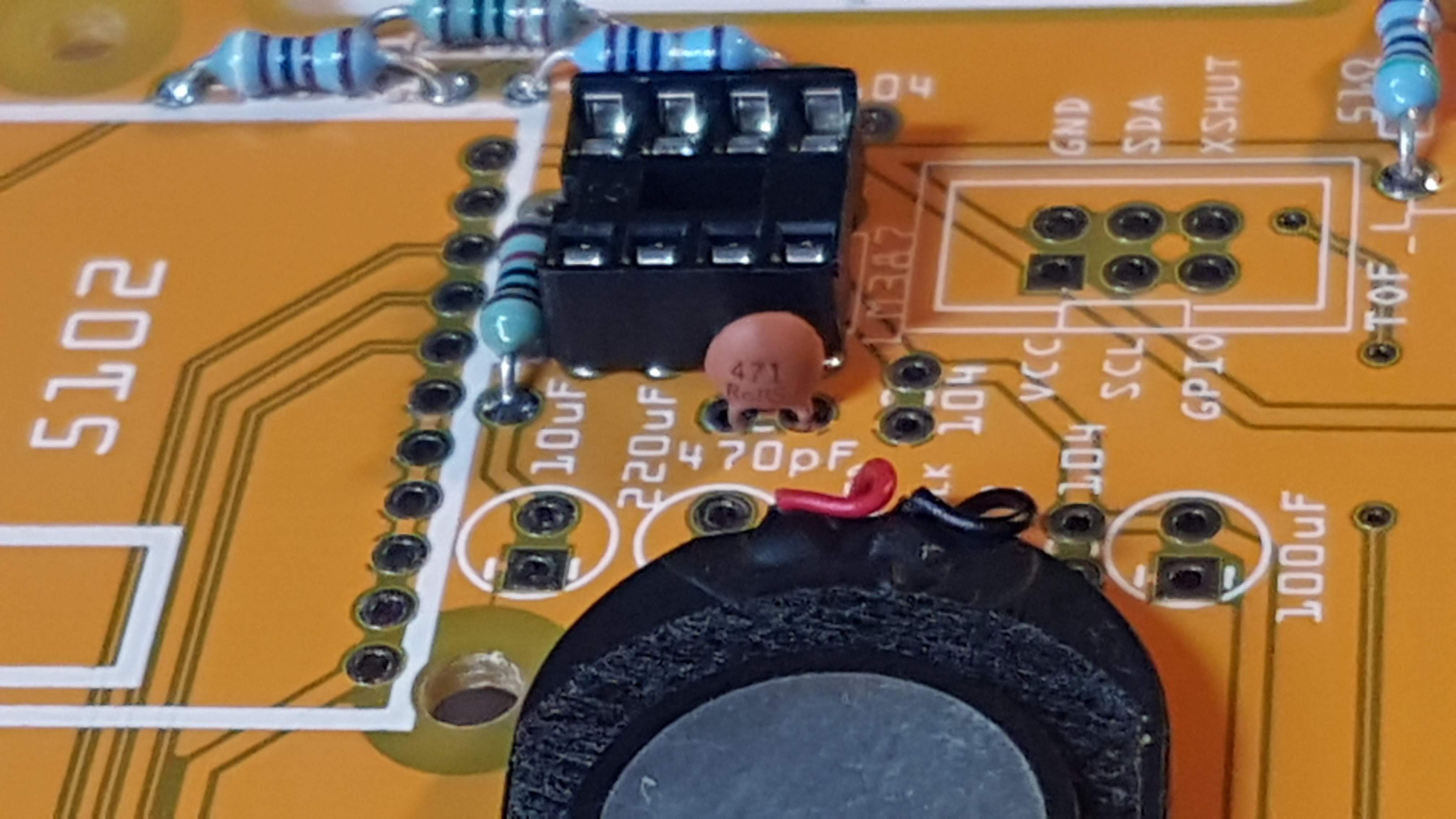
4. Ceramic Capacitors
Like the resistors, the ceramic caps are not polarized – they can go in either way around.
4.1 470pF Capacitor (471)
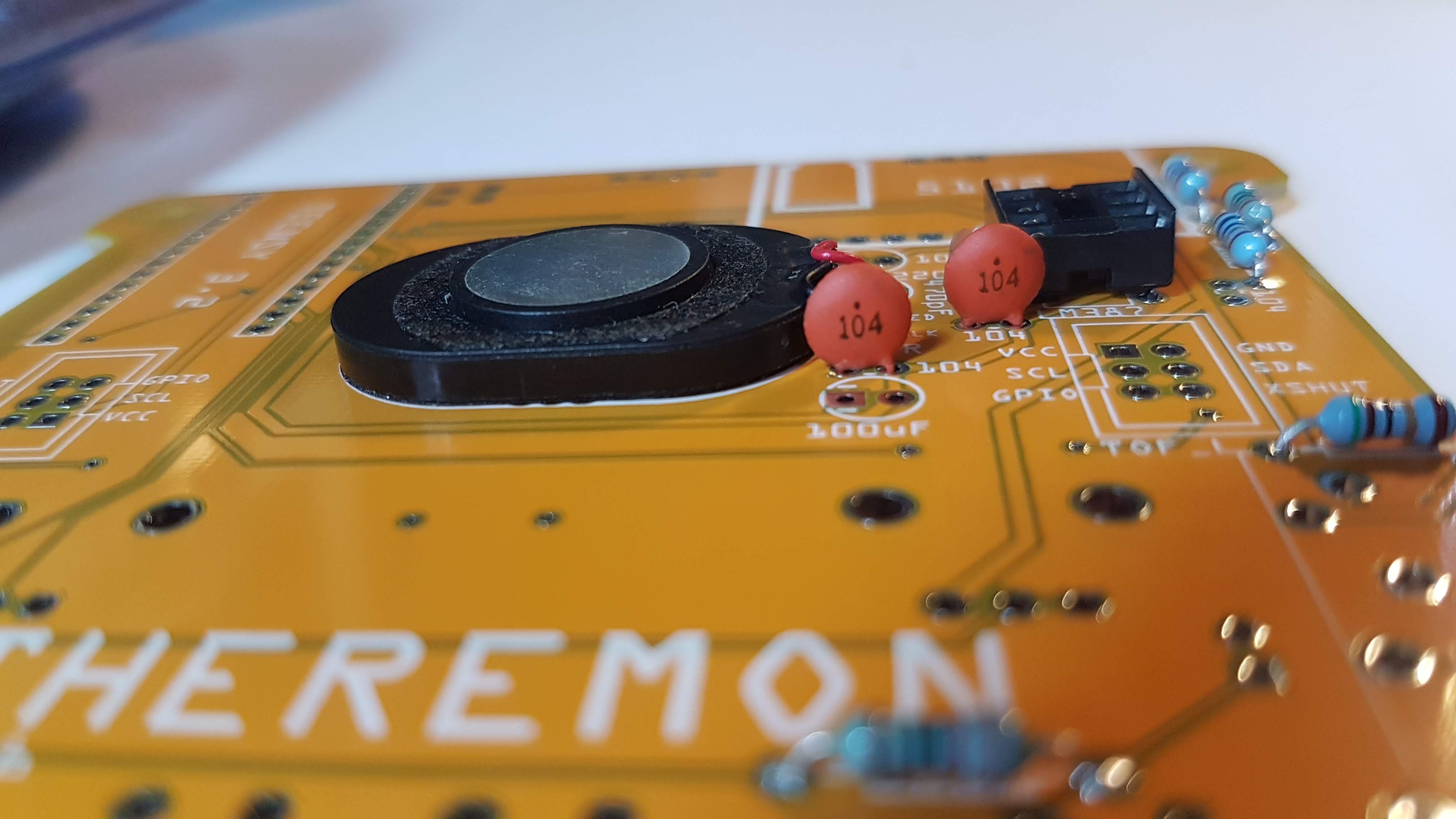
4.2 0.10uF Capacitor x 3 (104)
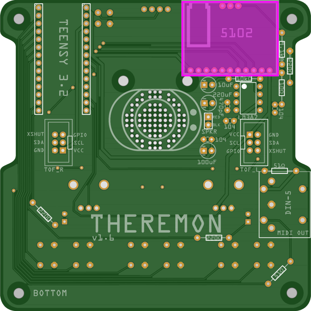
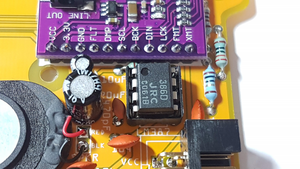
5. PCM5102A DAC Board
The PCM5102A DAC breakout board communicates with the Teensy over the I2S serial bus, and provides far better audio quality than I was able to achieve with the Teensy’s built-in DAC.
Cut the provided provided single-row header into a 11p (pin) section and a 3p section. It’s probably best to solder headers to the DAC board in place – solder the headers to the DAC board first.
Flip the PCB over and solder the DAC board to the PCB.
After soldering, trim the header pins down with you edge cutter. I looks neater, but additionally there are two pins that can interfere with the OLED if you don’t trim the header pins.
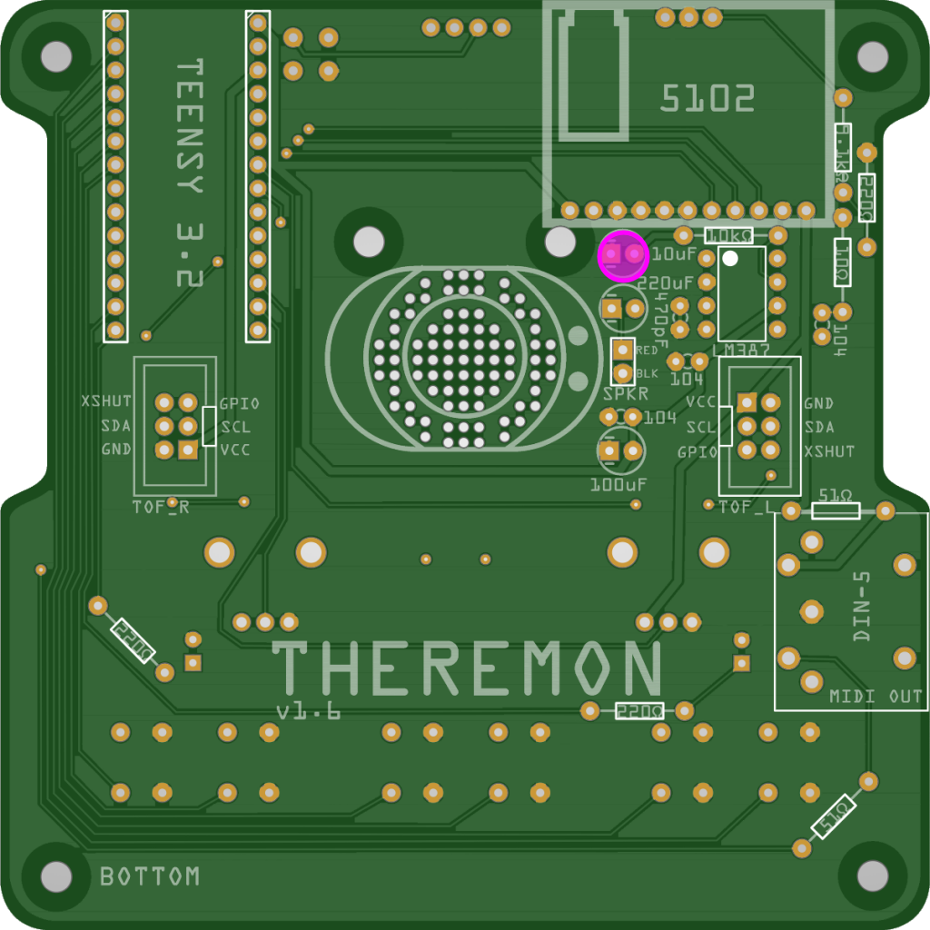
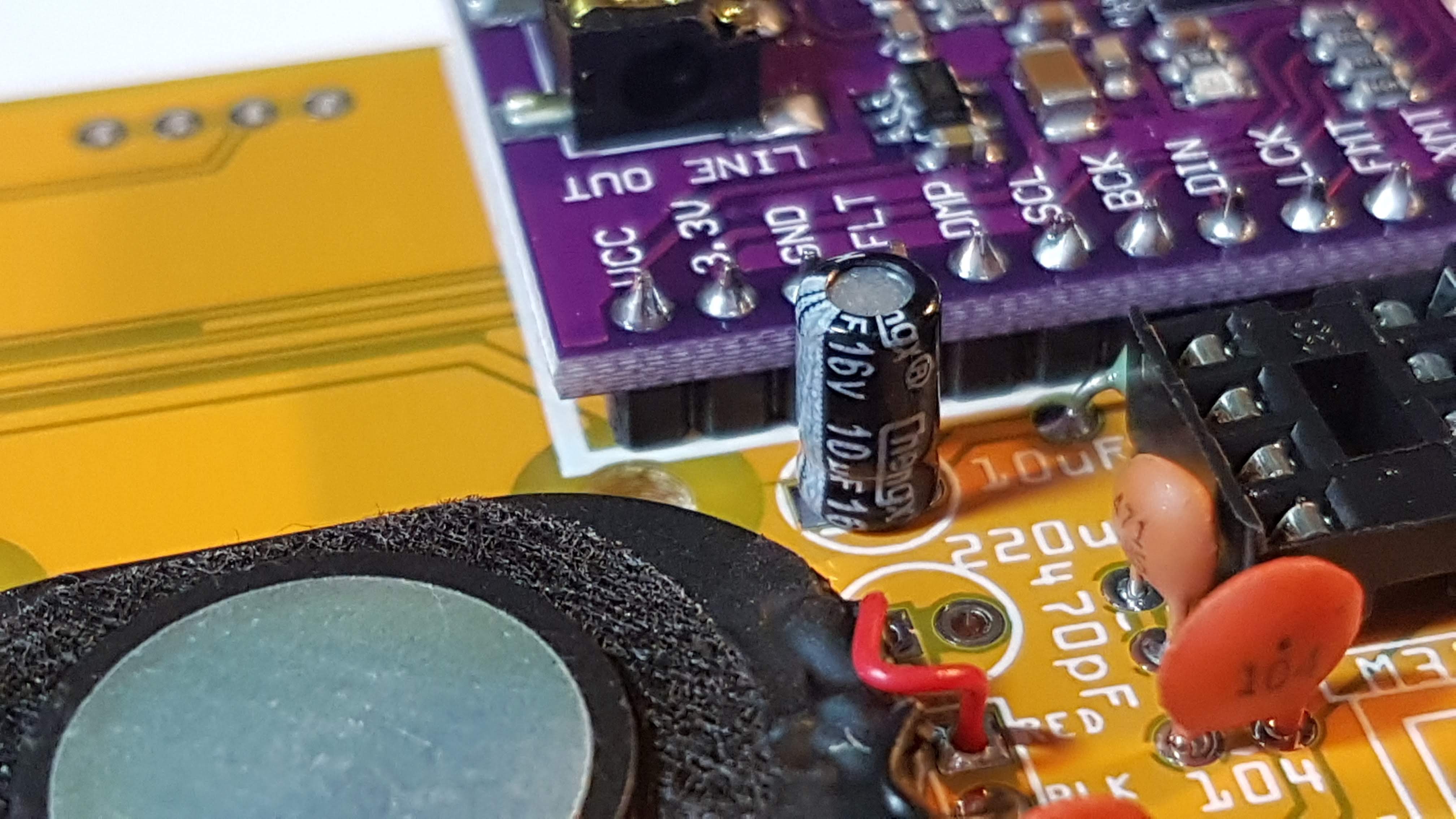
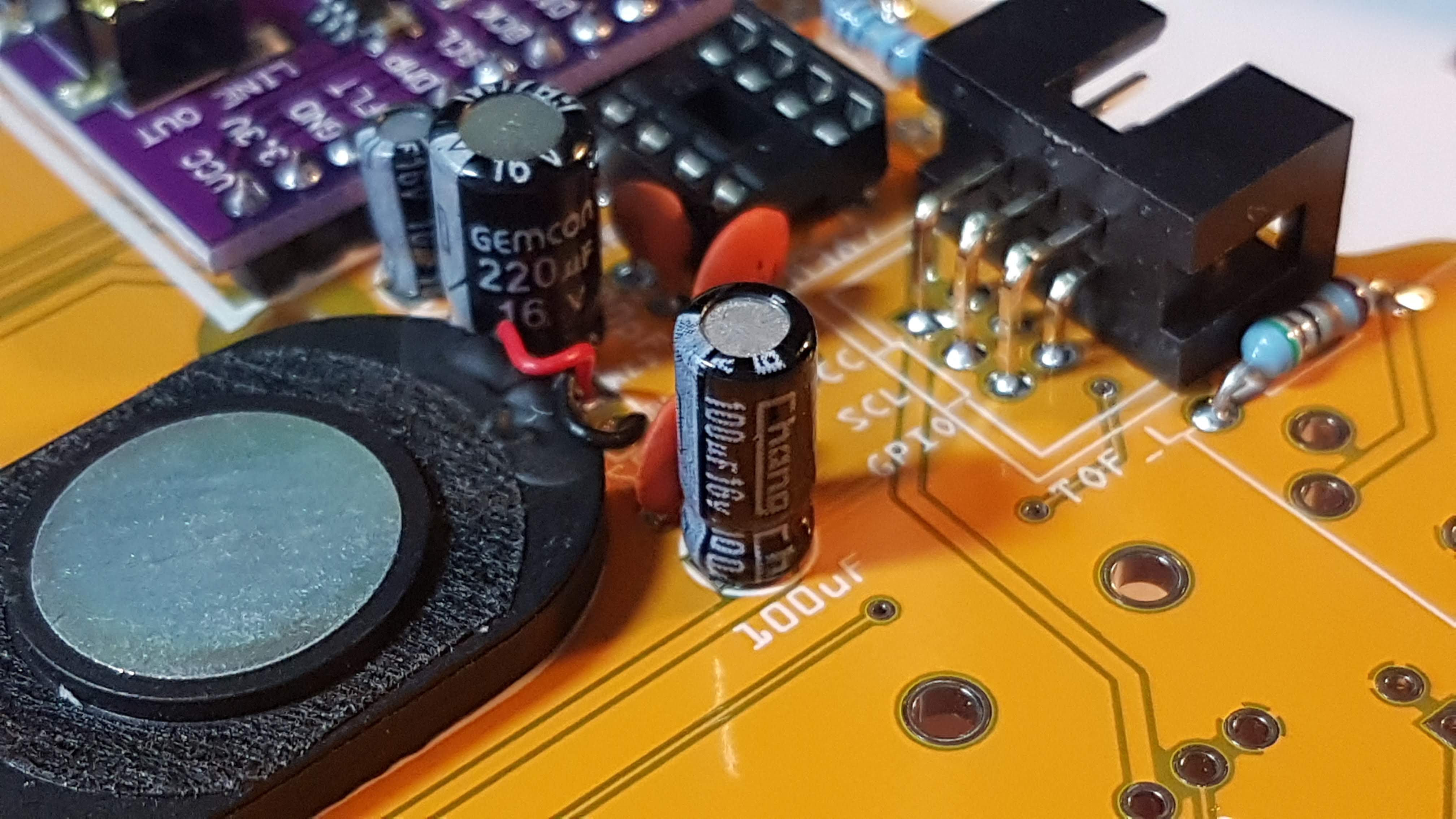
6. Electrolytic Capacitors
Heads-up! Electrolytic caps are polarized, so mind the orientation. The leg on the side of the cap that has the white line running down it (marked with –) goes to the square pad with two lines on either side.
6.1 10uF
The value is marked on the body, but the 10uF is also the smallest of the three electrolytic caps.
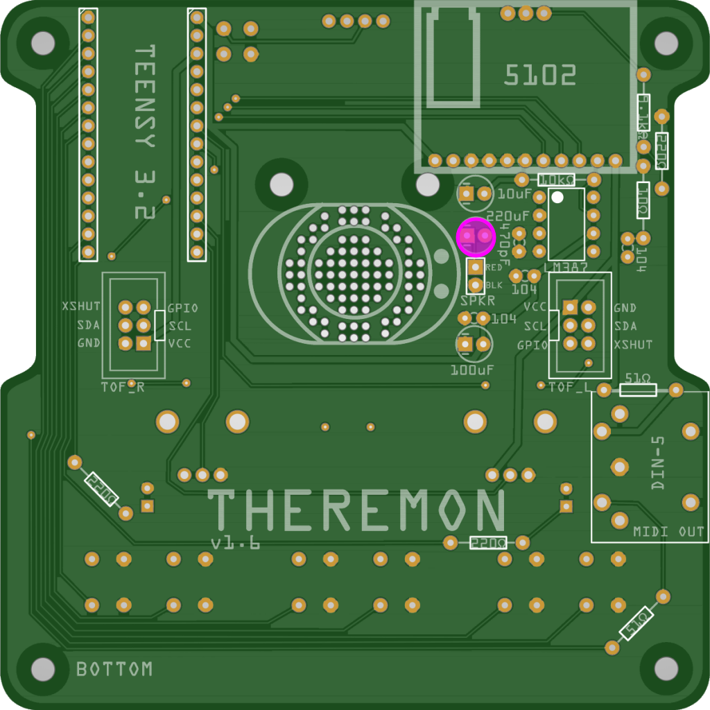
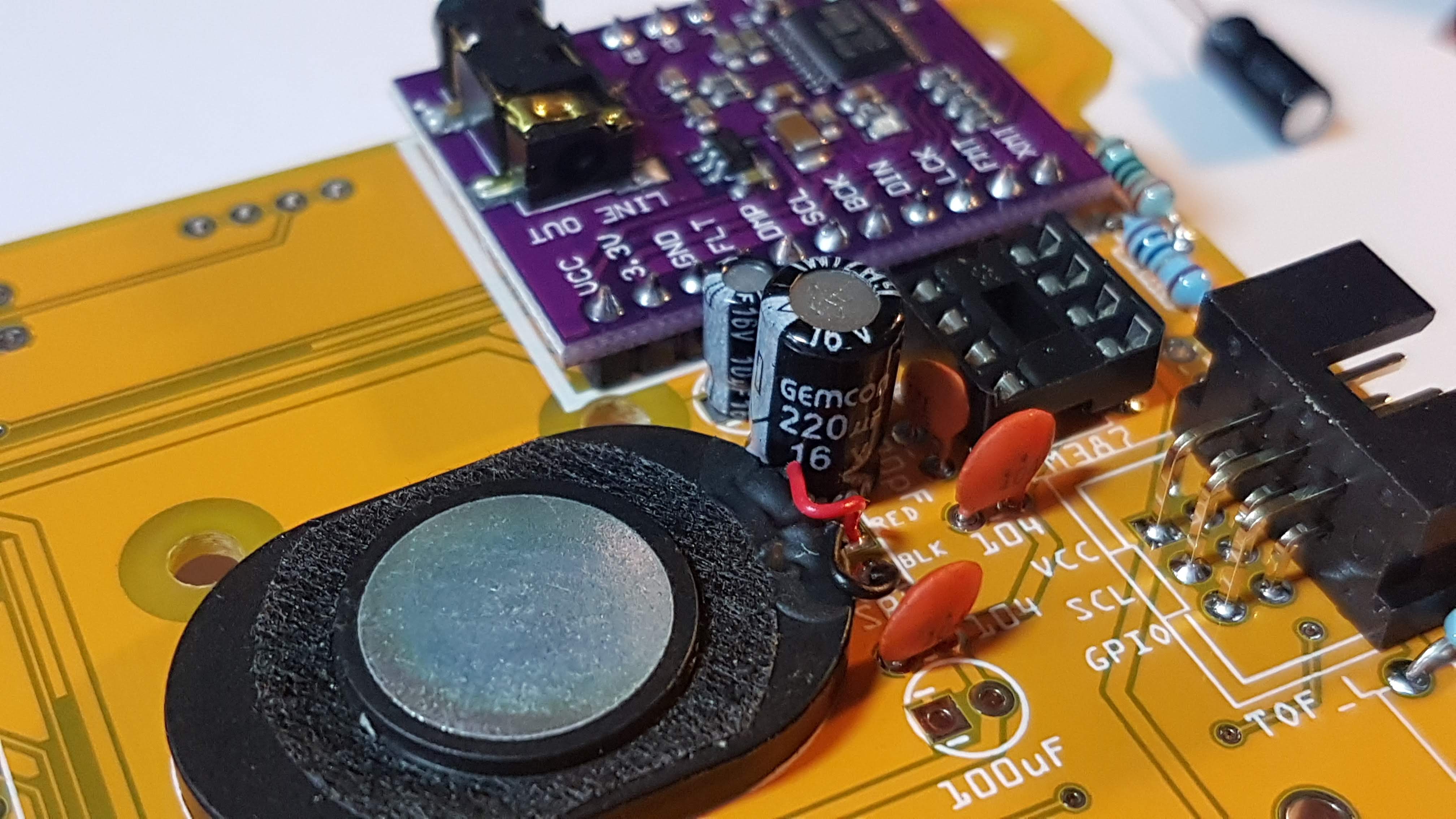
6.2 220uF
The 220uF is the biggest.
6.3 100uF
And the 100uF is medium sized.
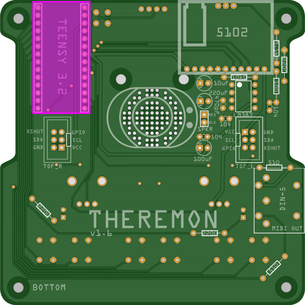
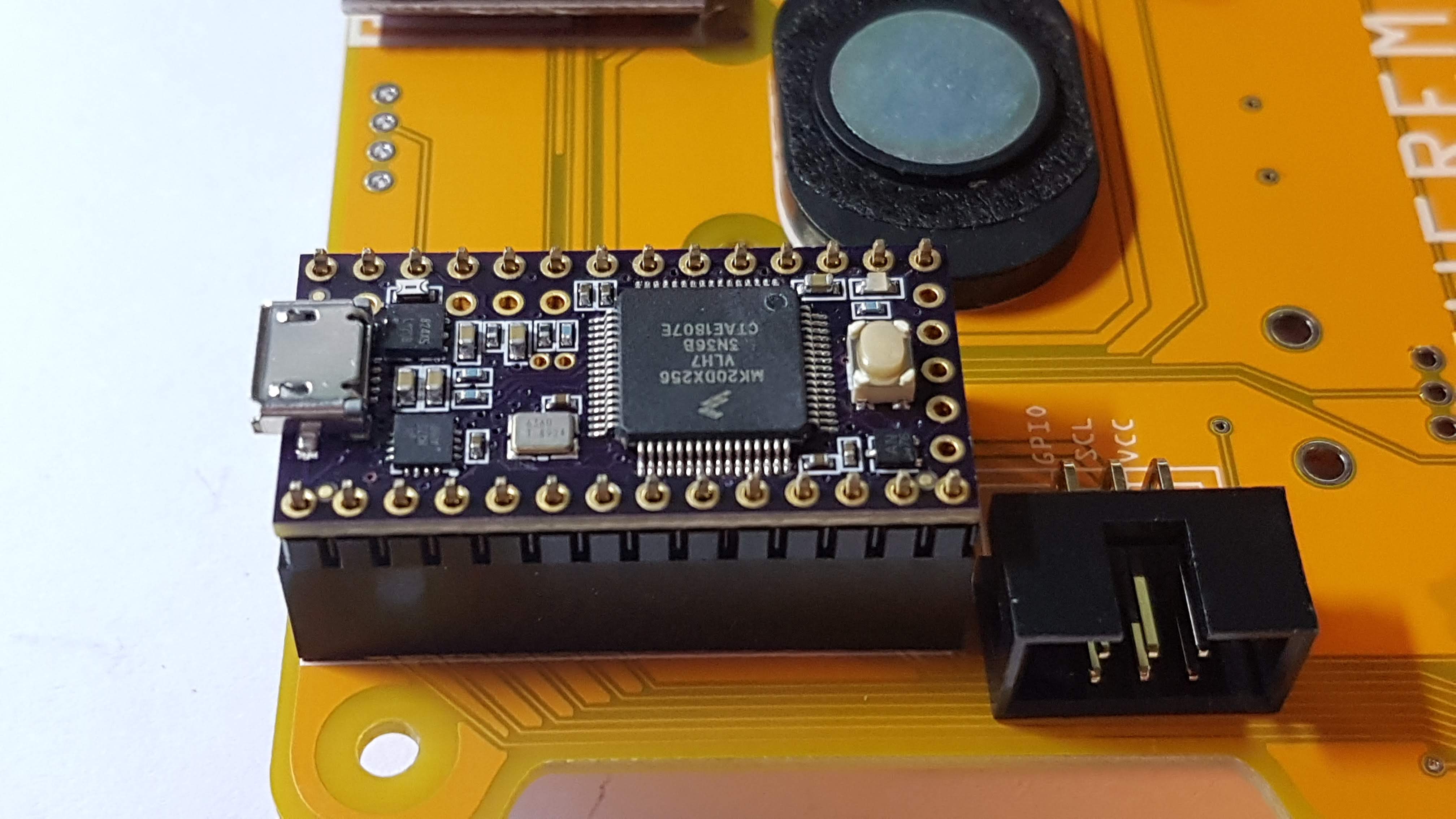
7. Teensy 3.2
The Teensy 3.2 is Theremon’s brain! If you picked the option for a kit that includes the Teensy, yours will already be flashed with the latest firmware at the time of shipping. It might be worth checking if there’s been a firmware update. Flashing new firmware is super easy (love you, Teensy!). Instructions are on the Firmware page.
I find it easiest to insert the two 14p female headers on their silkscreened footprint, and to put the male headers into them. You’ll have received enough headers, though you may not find 2 x 14p stretches in one piece. Not to worry, just steal a pin or two from another piece and complete the 14p row. Next, put the Teensy down onto the male header pins and solder. In case it’s not obvious, the shorter side of the male header goes to the Teensy, and the longer side goes to the female header.
Flip the board over and solder the female headers to the board. There shouldn’t be an issue if you leave the Teensy attached for this step.
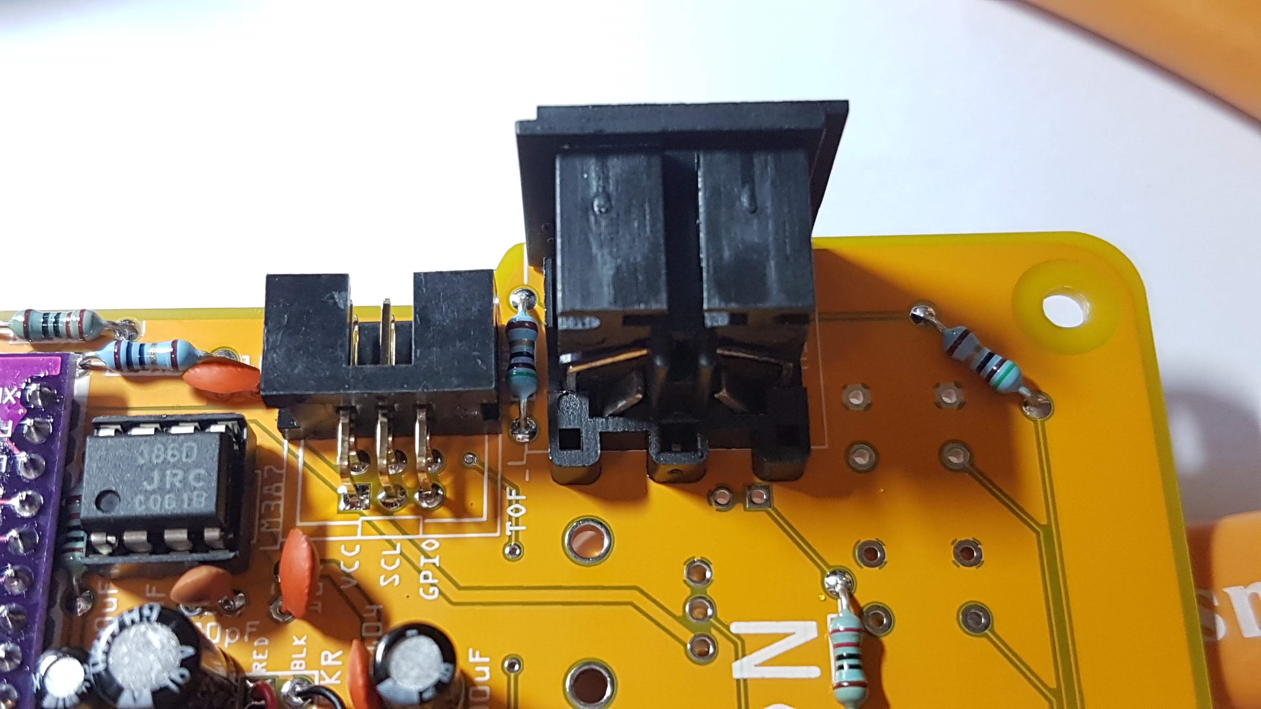
8. MIDI DIN
9. LM386 IC
No soldering required. Just bend the legs inward a little so the IC fits easily, then push it home. Check the orientation.
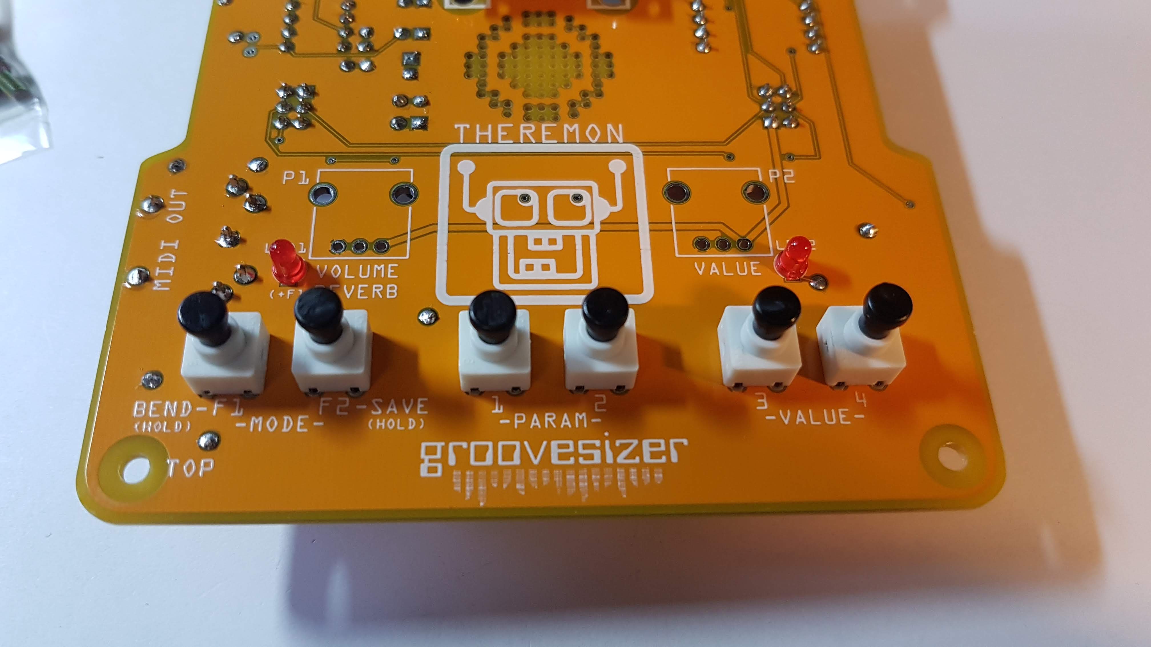
PCB TOP
Time to flip the board over and populate the components on top.
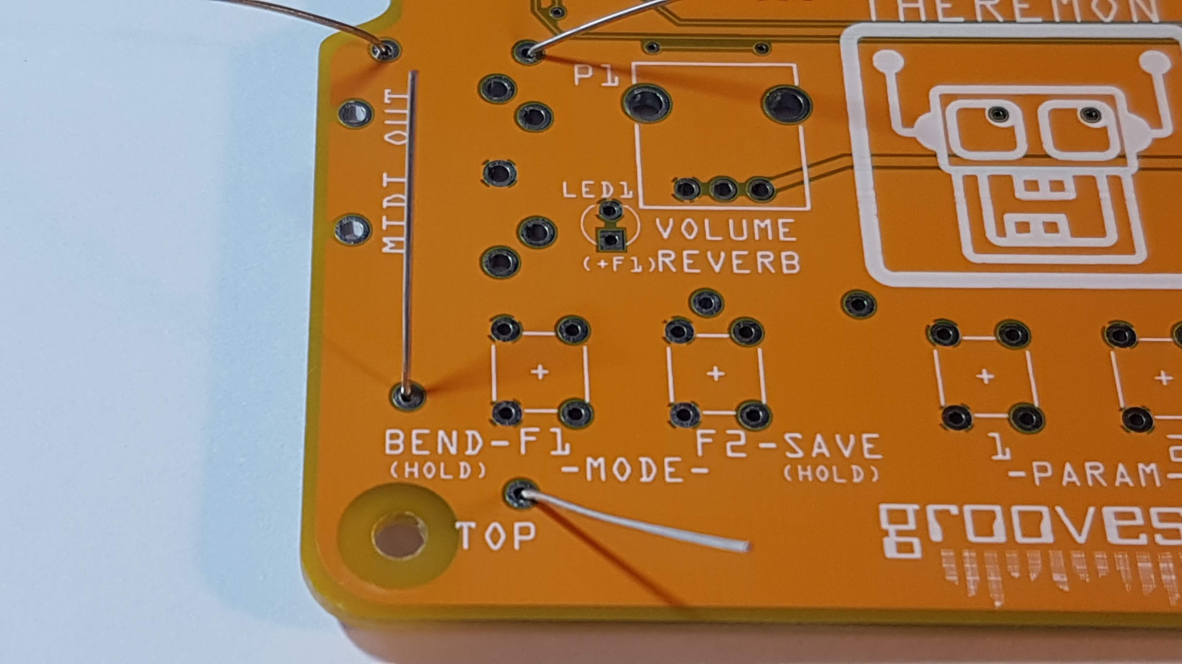
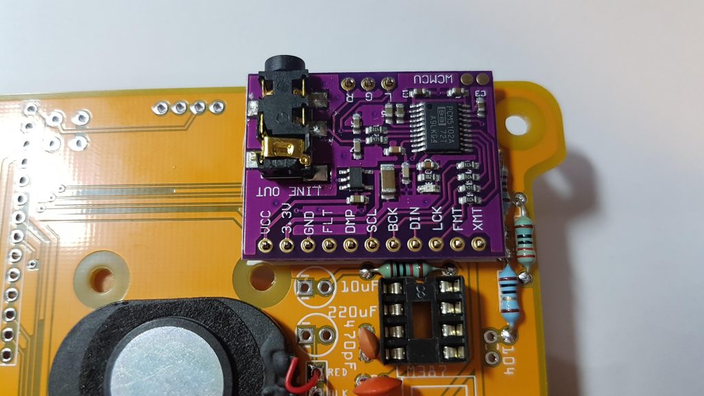
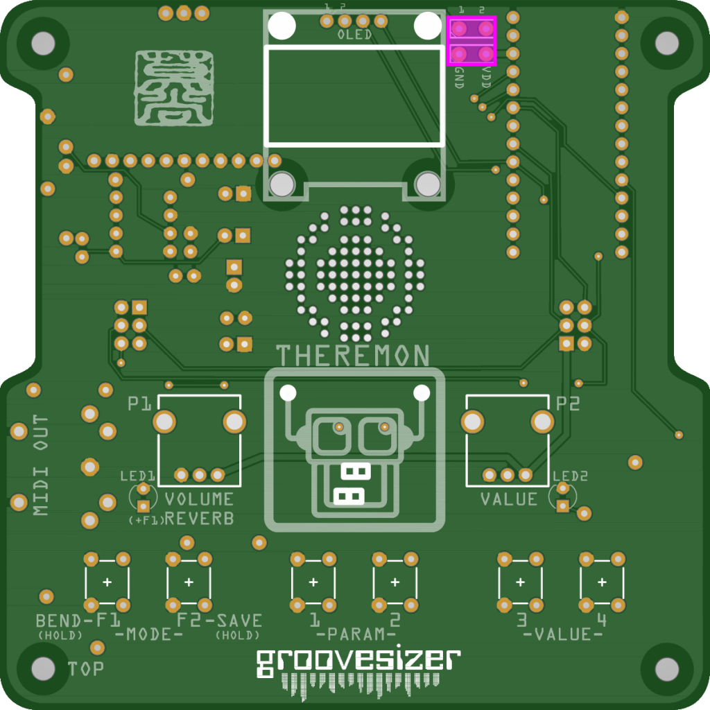
10. OLED Jumpers x 2
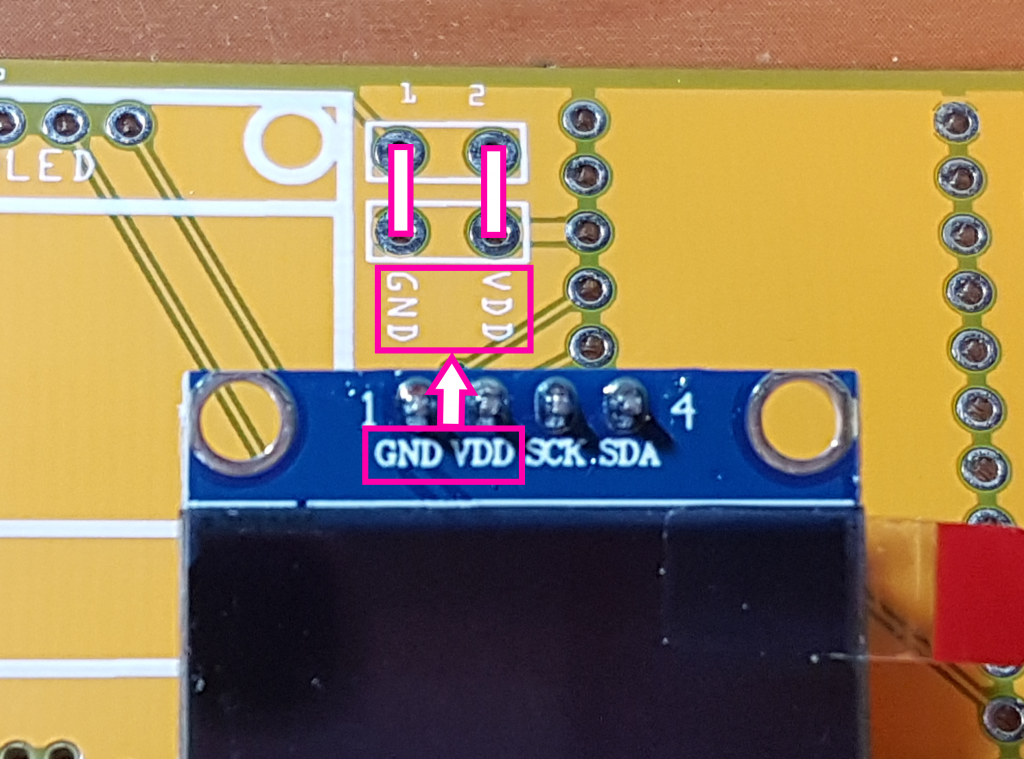
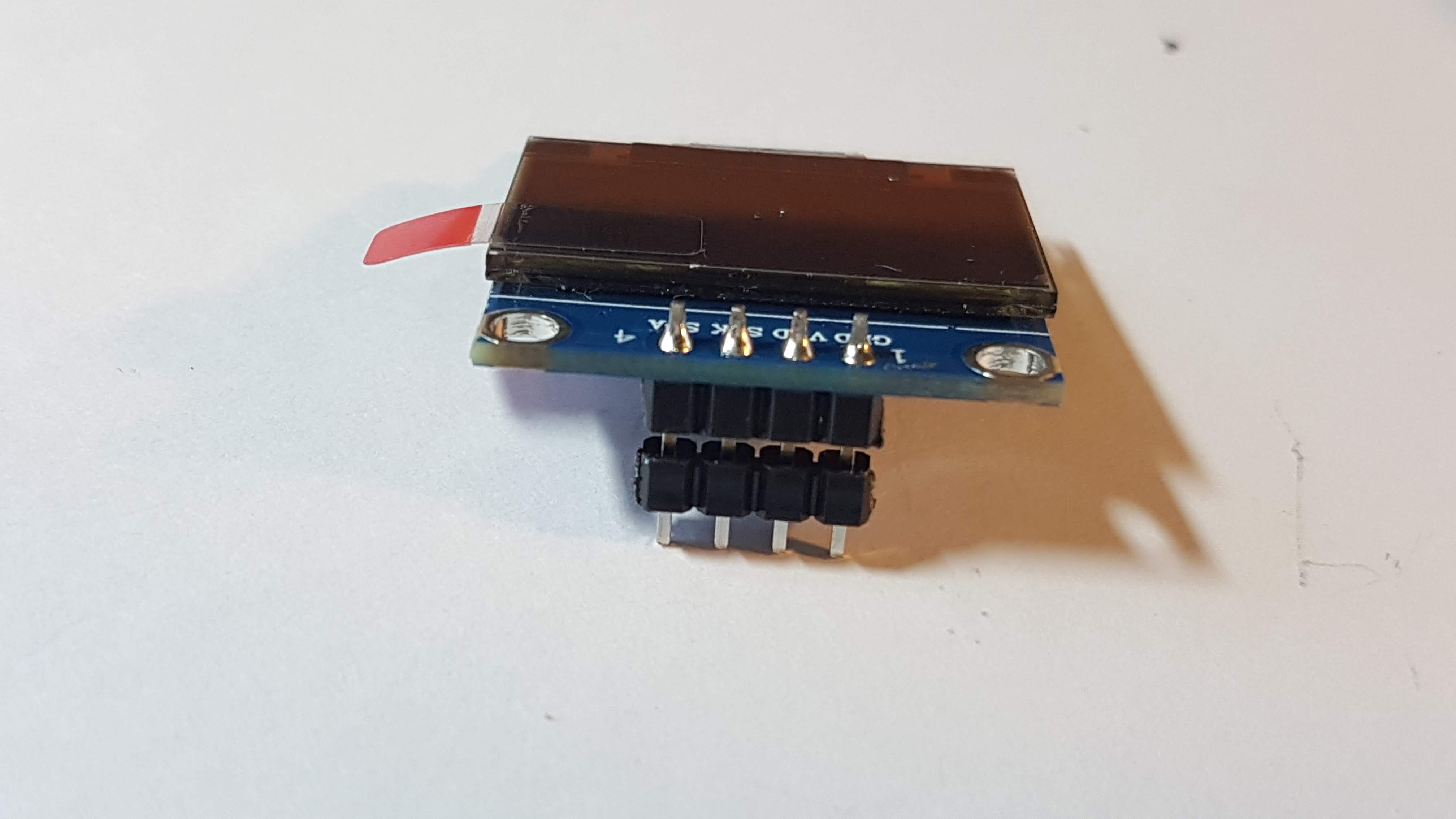
While sourcing parts for Theremon, I noticed that many OLED units have GND and VDD pins swapped around. In order to accommodate both types, I’ve added jumper pads.
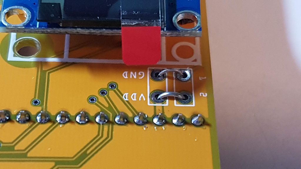
Compare the legending of the pins on the OLED you’ve received with the silkscreen on the PCB. If GND is on the left on your OLED, use cut off legs from some of the resistors to connect the GND pad on the PCB to the pad labeled 1 above it. Similarly, connect VDD to the pad labeled 2. Conversely, if your OLED unit has VDD on the left, connect the GND pad on the PCB to pad 2, and VDD to pad 1. This will make an X shape, so it’s best to put one jumper on the top side of the board and the other jumper on the bottom side so you don’t create a short.
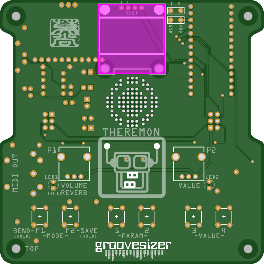
11. OLED
We want to raise the OLED a little so it sits closer to the surface of the acrylic enclosure. You should have some male headers left over. Cut a 4p section, remove the metal pins with pliers, then slide the plastic bit up over the header on the OLED so the header has a double row of plastic retainers – in the pic above there is a gap between the two black plastic spacers, but you want them right up against each other.
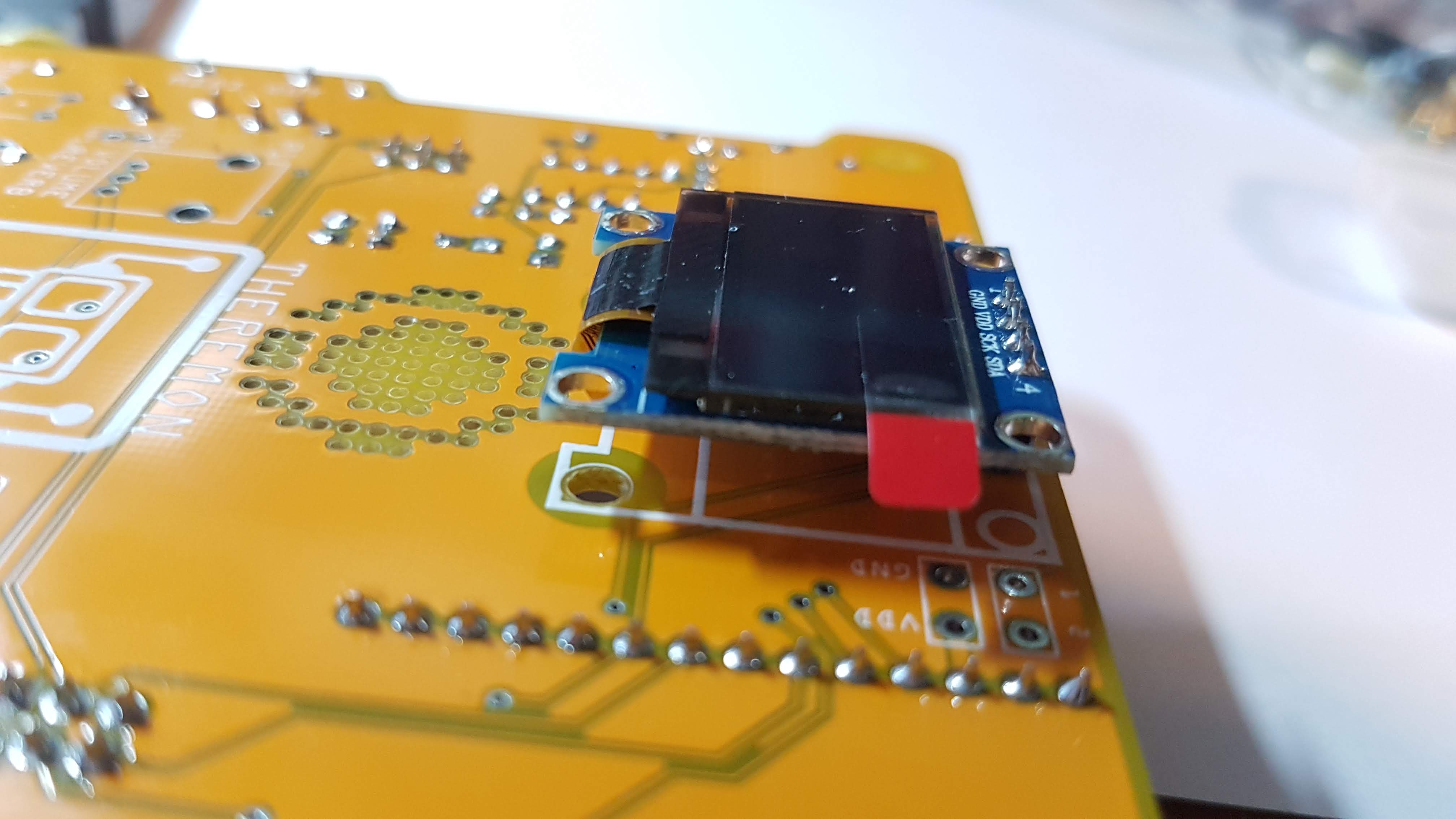
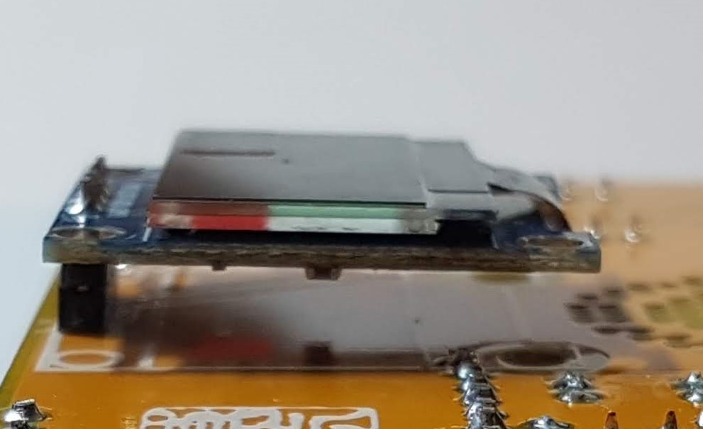
Take care that the OLED is parallel to PCB when you solder it – do one leg first so you can reheat the leg and reposition before soldering the other legs.
The OLED just sits like this without a support on the bottom side, but the OLED unit is so light that it’s not an issue.
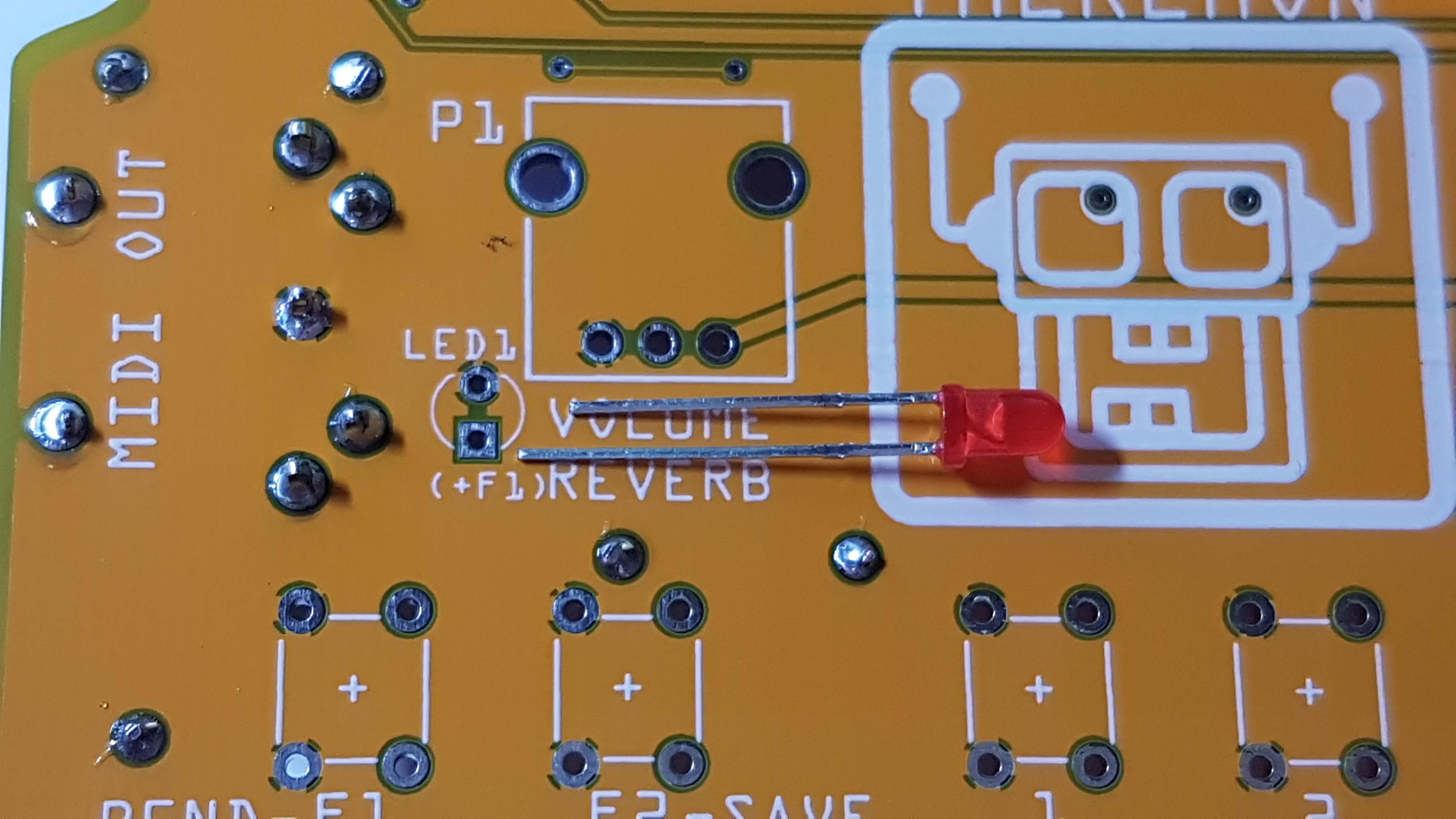
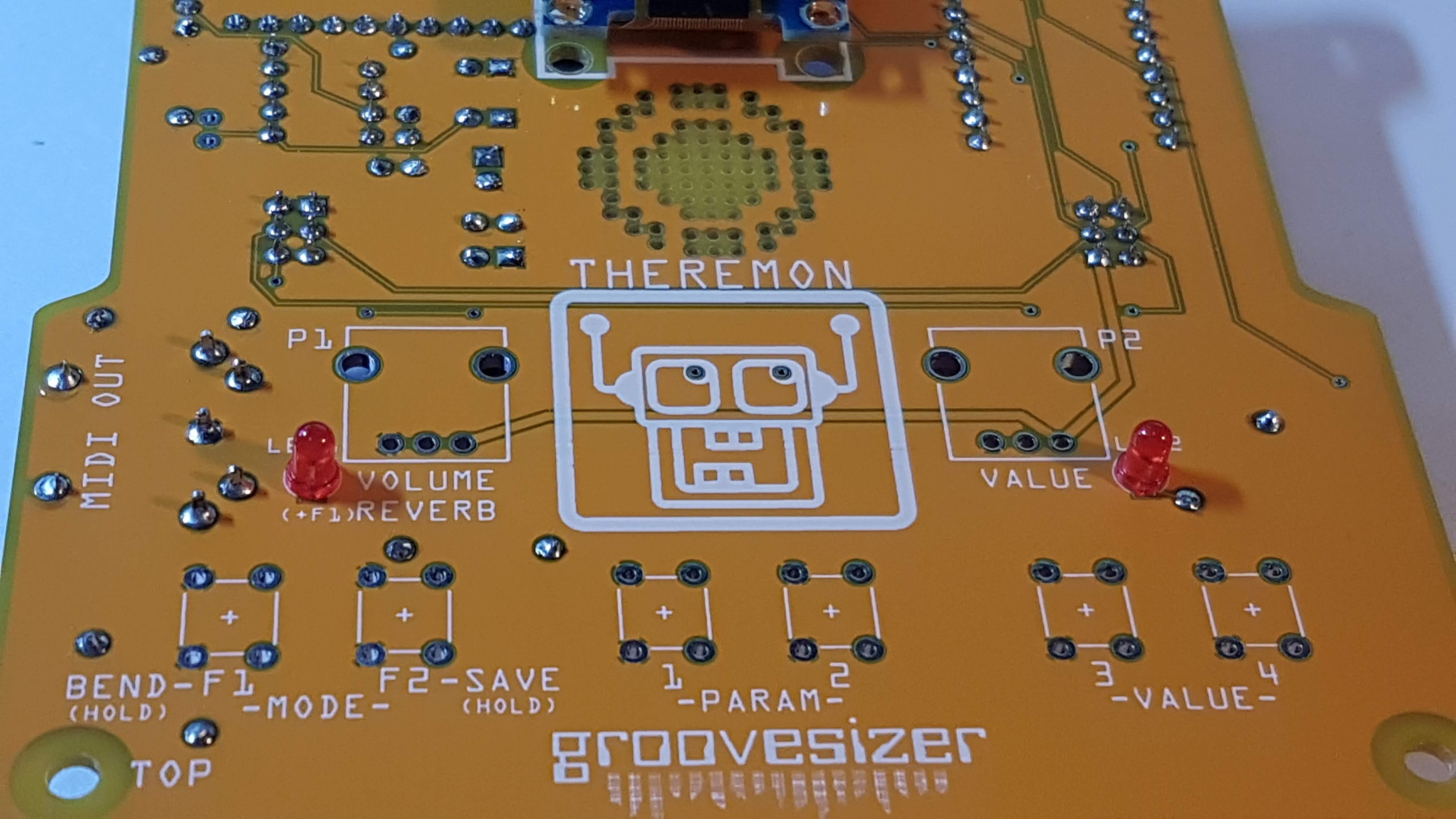
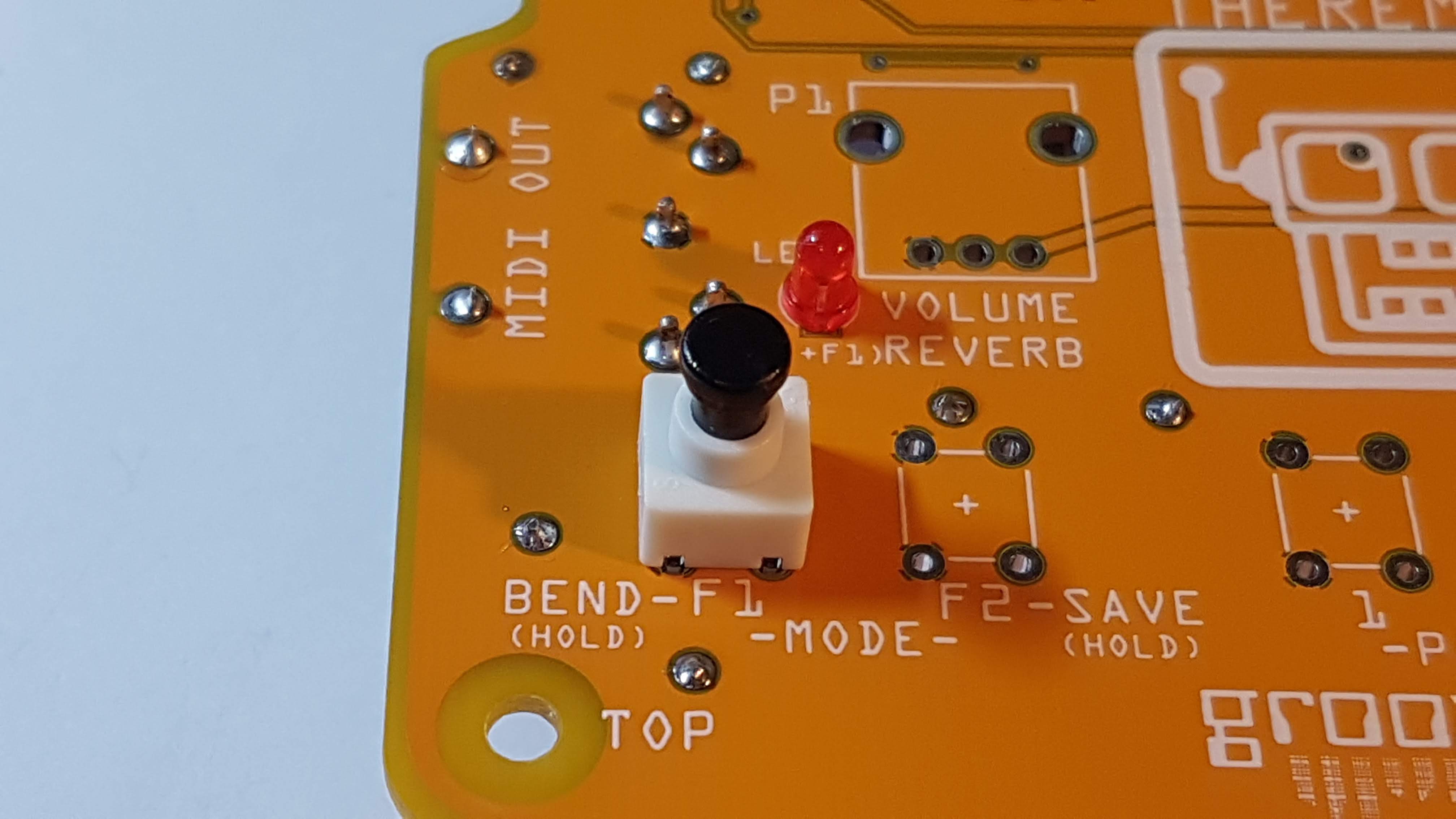
12. LEDS x 2
The longer leg of the LED goes to the square pad, and the shorter goes to the round pad.
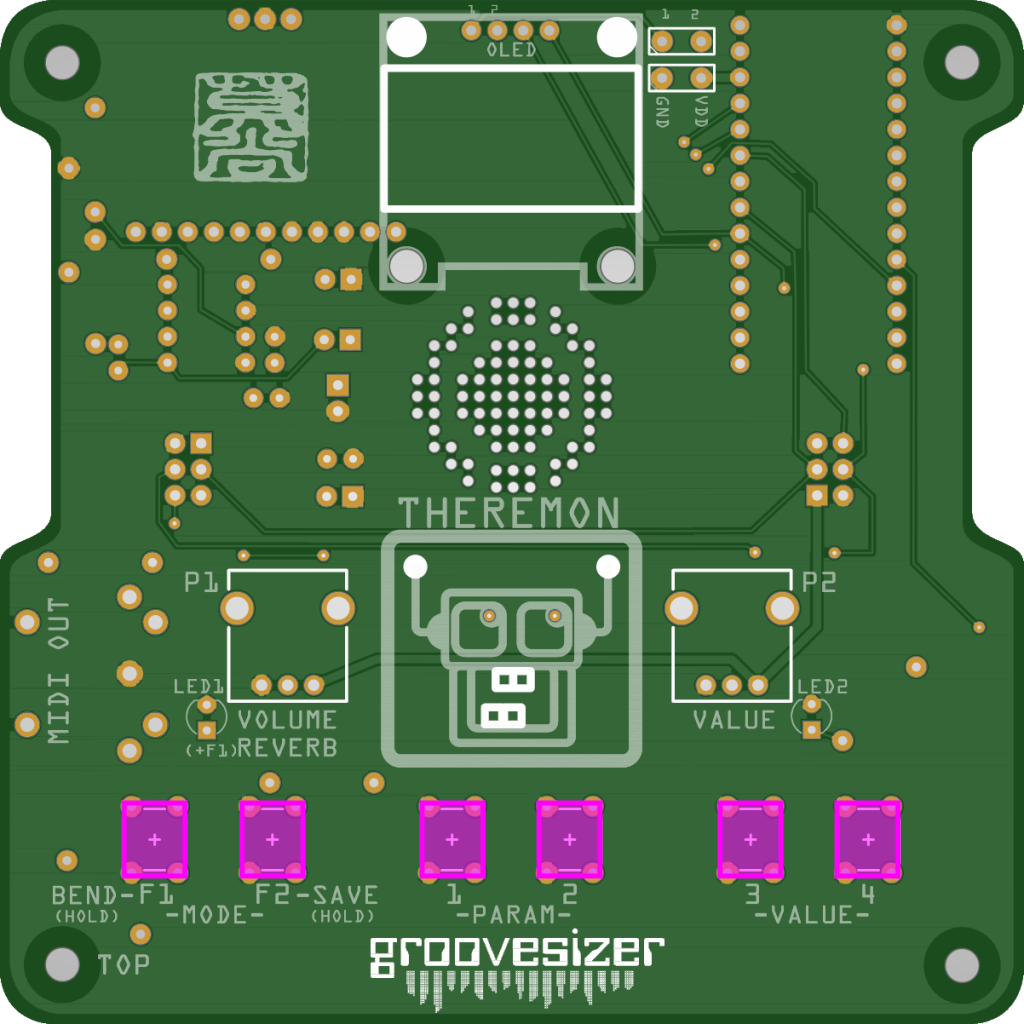
13. Buttons x 6
The footprint for the buttons is rectangular. The notches in the body of the switch where the legs come out align with the shorter sides of the rectangle. There’s no front and back to the switch, so it can go in either of the two ways around that fits the footprint.
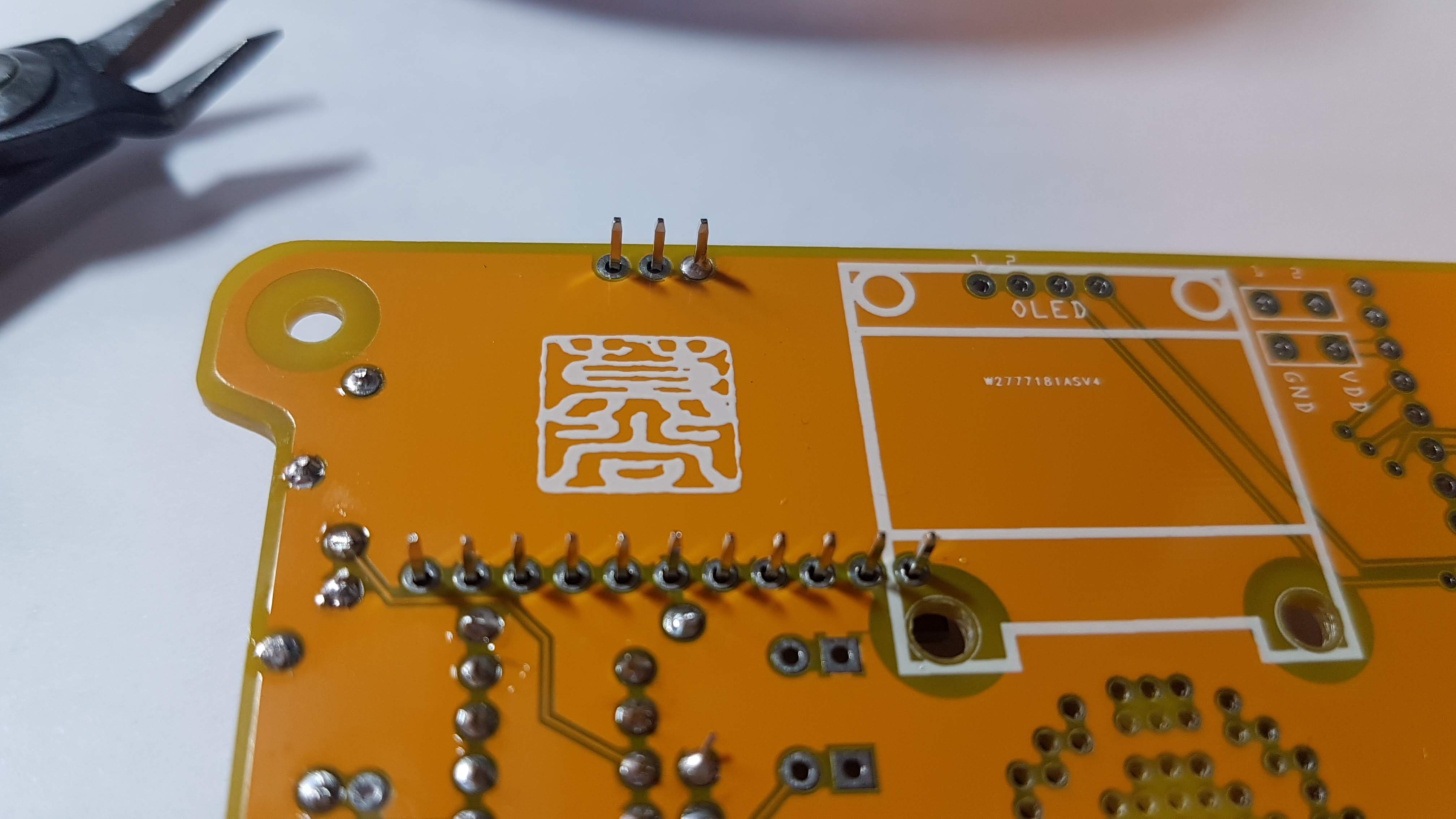
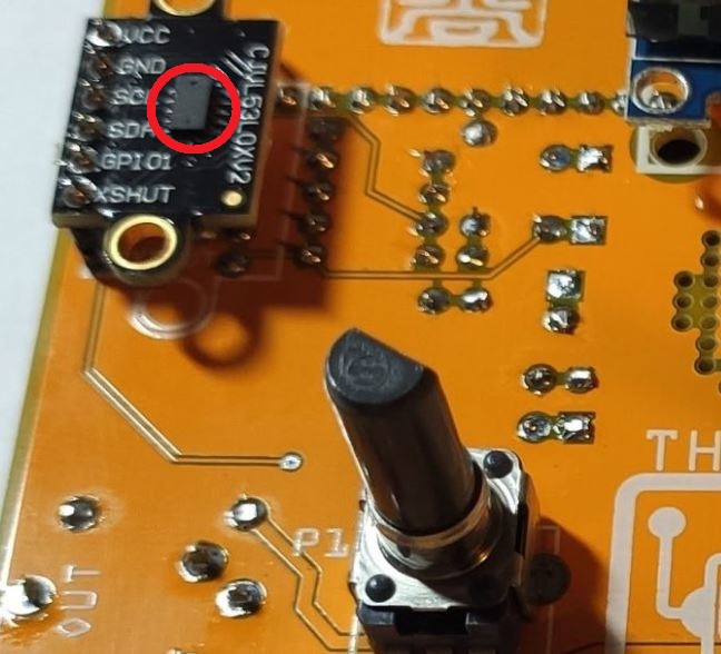
14. Time of Flight (ToF) Distance Sensors x 2
Theremon has two Time of Flight sensors to measure the distance between the player’s hands and the instrument (Adafruit is a great resource to learn more about the VL53L0X sensors we’re using).
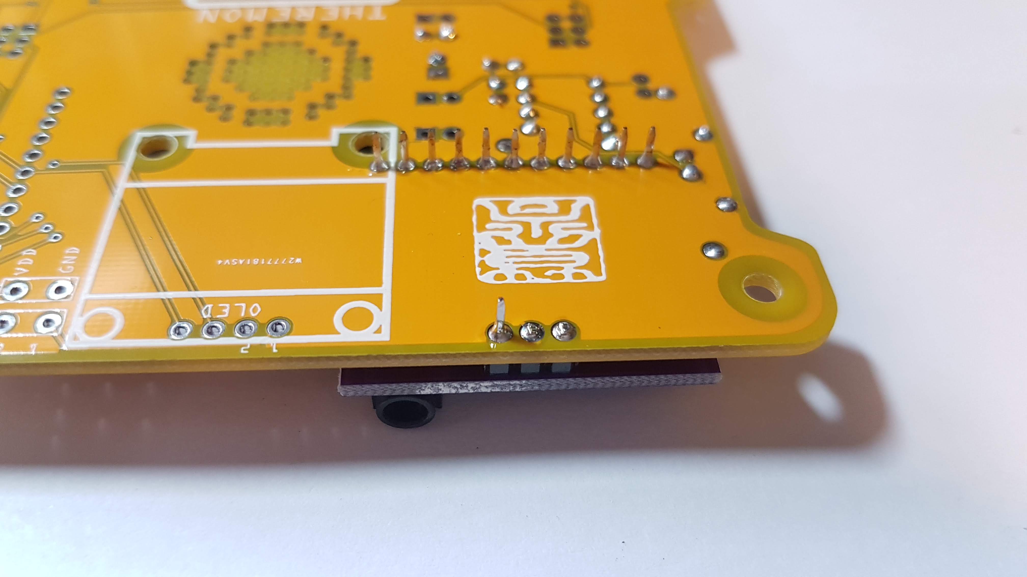
Mind the orientation here – the ToF sensor ICs should face up, away from the main yellow PCB. You should notice two tiny holes in the sensor ICs – one emits laser light, and the other receives reflected light back. Should your Theremon ever behave strangely, try blowing on the sensors – dust can partly obscure the holes leading to weird measurements.
We’re doing the same thing we did with the OLED to raise the ToF sensor above the PCB. After this step, you won’t need any more headers, so feel free to cannibalize the remaining headers for their plastic retainers.
Align the part with the silkscreen outline. Tack one leg, then make sure the sensor is parallel to the main PCB before soldering the other legs.
Repeat the process for the ToF sensor on the opposite side.
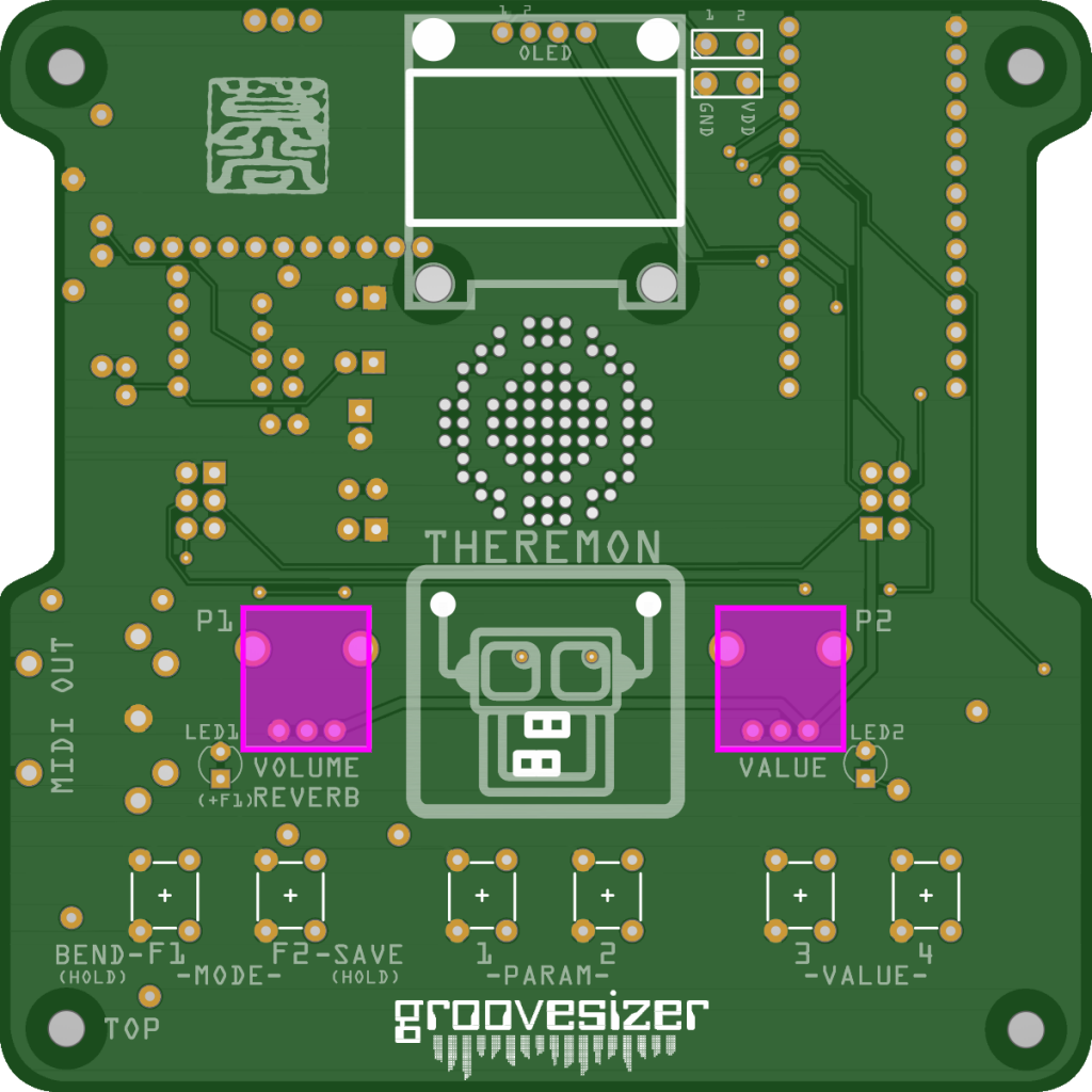
15. Potentiometers x 2
The pots only fit one way, though be sure they’re straight when you solder.
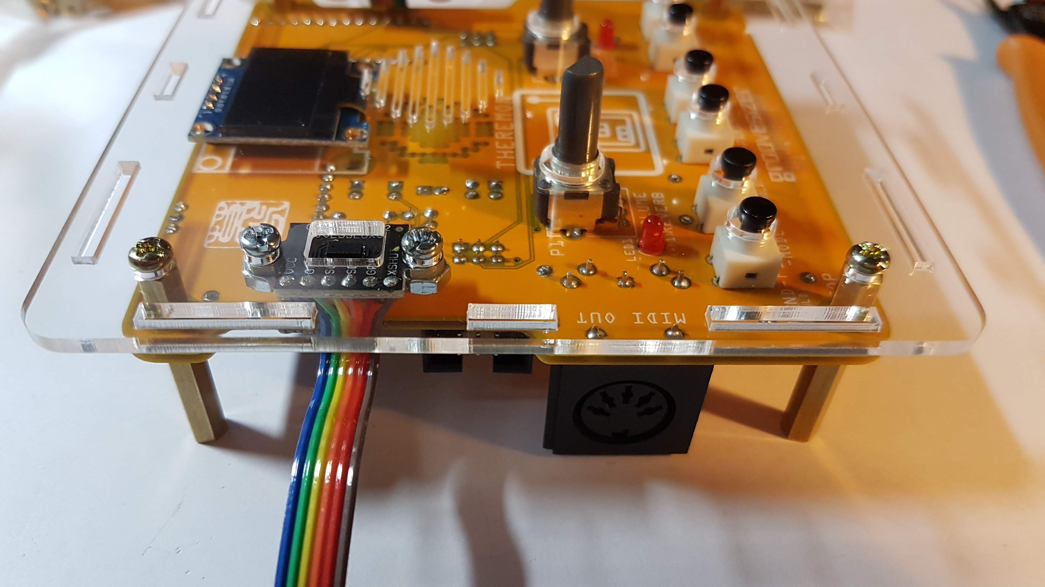
16. Enclosure
Remove the protective paper from the top enclosure plate – it’s the large ones with holes for the sensors, pots and buttons.
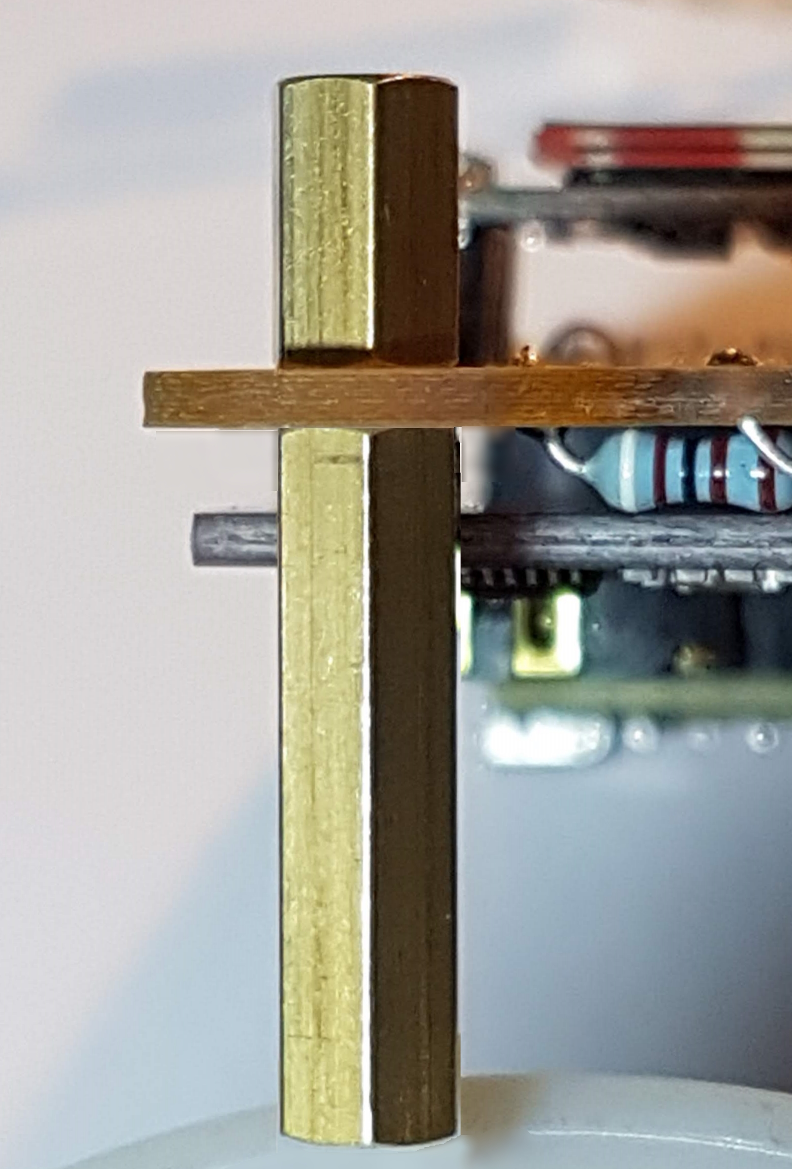
Screw in the hex spacers on the corners of the PCB. The shorter one is at the top of the board.
Screw the top plate with the mounted ToF sensors to the hex spacer standoffs. Don’t be like me and forget to the screen protector from the OLED ;^/
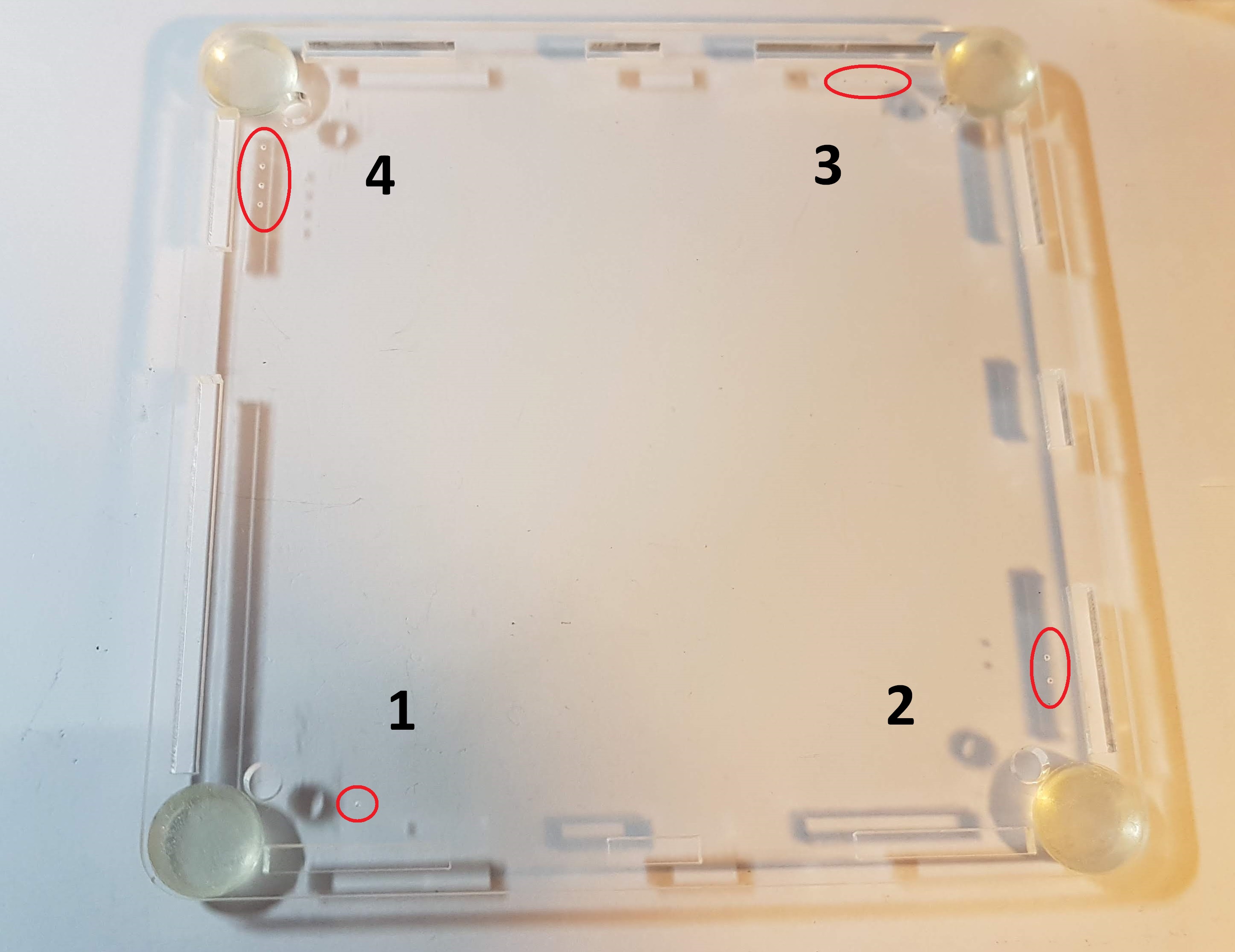
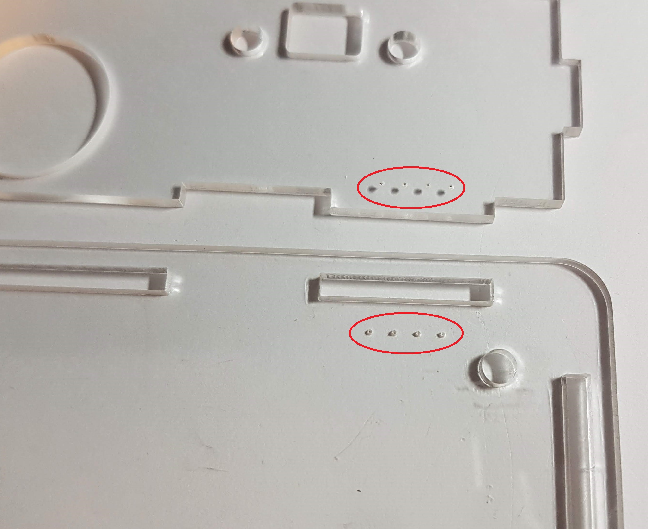
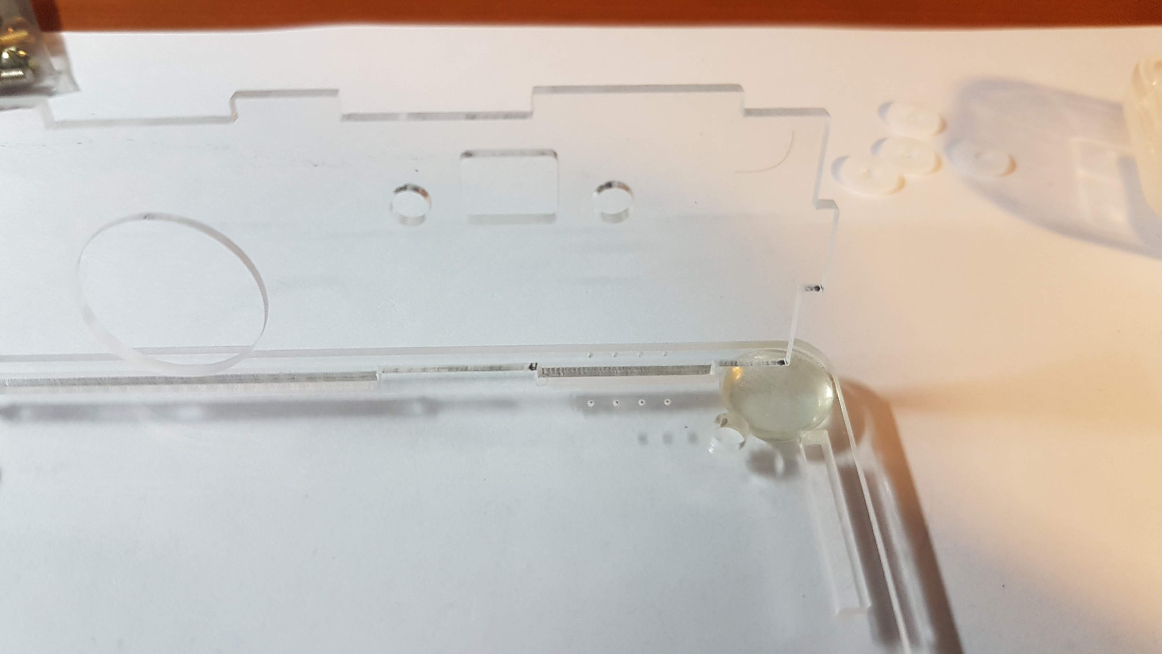
Remove the paper backing from the bottom plate. Make sure the right side is up before you start adding the side walls. The plate is etched with dots to help align with the side walls. Match up the number of dots to the pic above to get the right side on top.
Align the ridges and slots with the same number of dots when assembling the side walls.
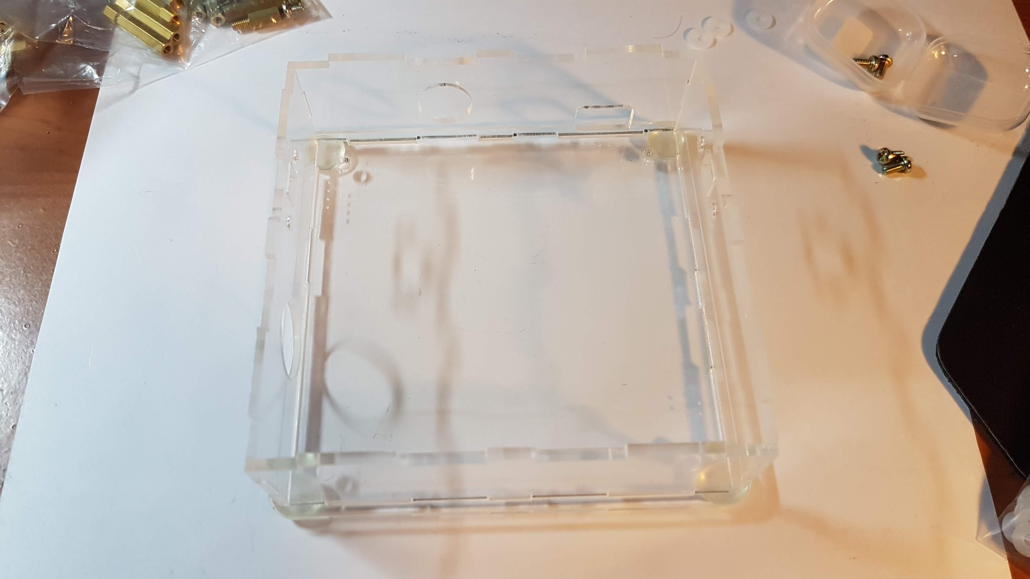
Once the walls are build up, drop the top plate and pcb assembly into it and push the slots home onto the ridges.
Flip the case over and screw the standoffs to the bottom plate.
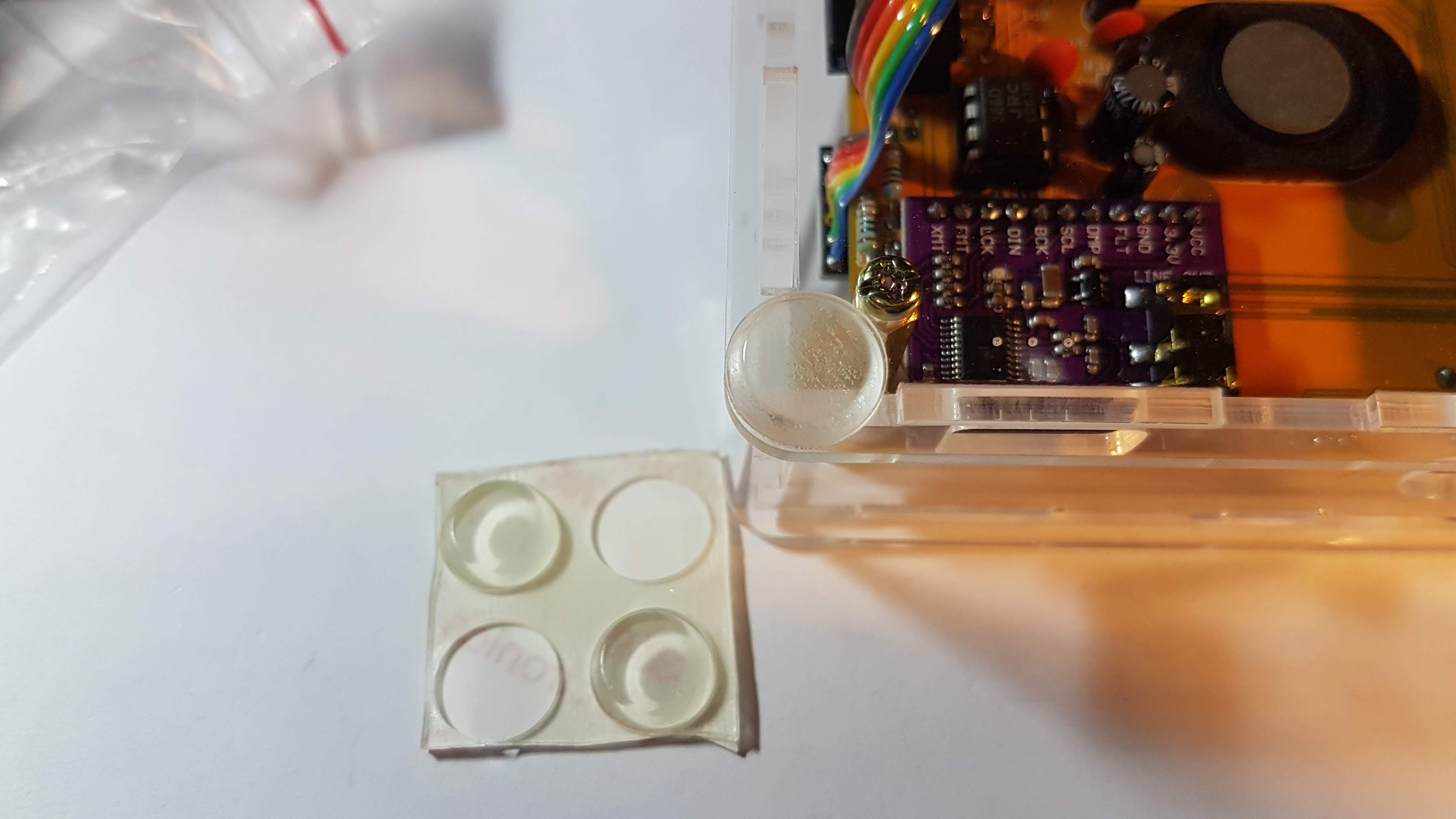
Then add the bumper feet to the four corners.
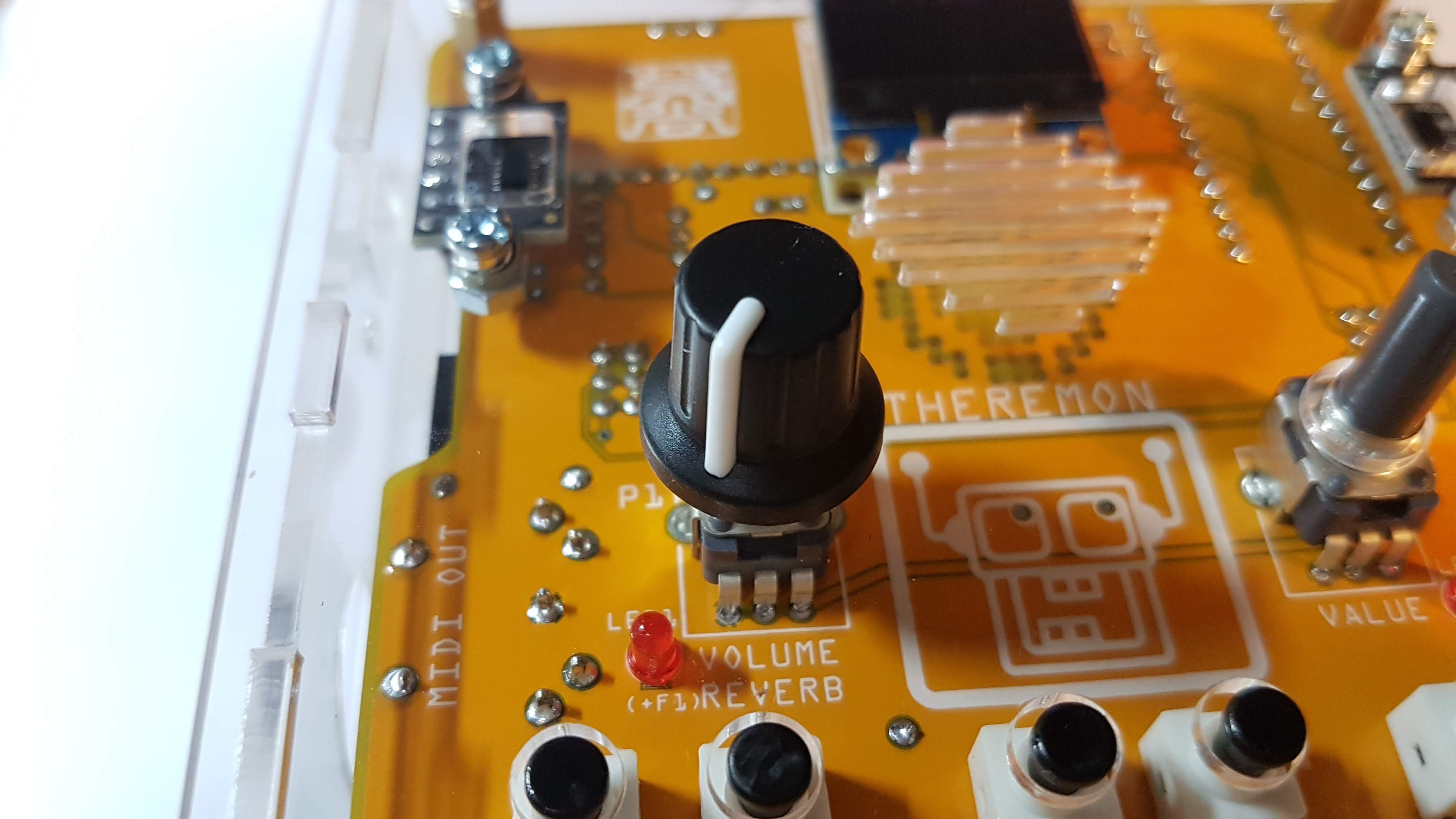
Push the knobs onto the potentiometer shafts.
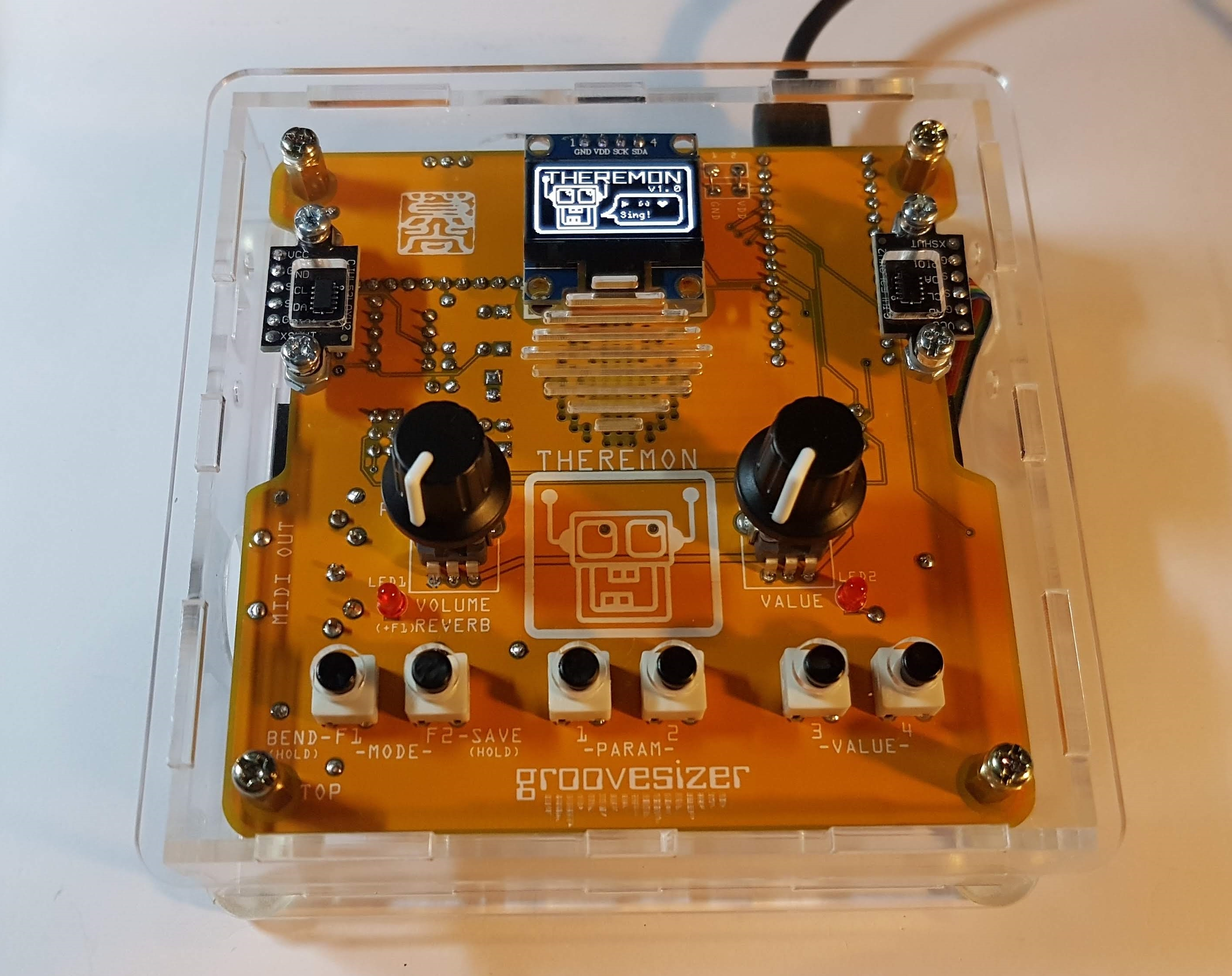
Congratulations, you’re done!
Plug in a micro USB cable attached to a 5V smartphone charger (the same cable and charger as most Android phones), and off you go. Theremon reporting for duty!