If you’ve never soldered through-hole electronics before, I suggest you give yourself a quick primer with one of the numerous through-hole soldering tutorials on YouTube, like this one.
Importantly, take all the time you need – there’s no rush. And work in a well-ventilated space.
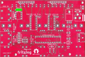
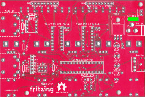
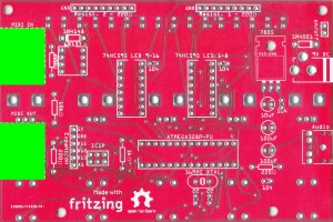
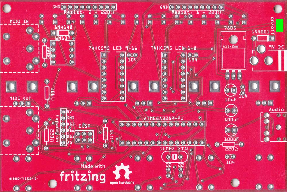
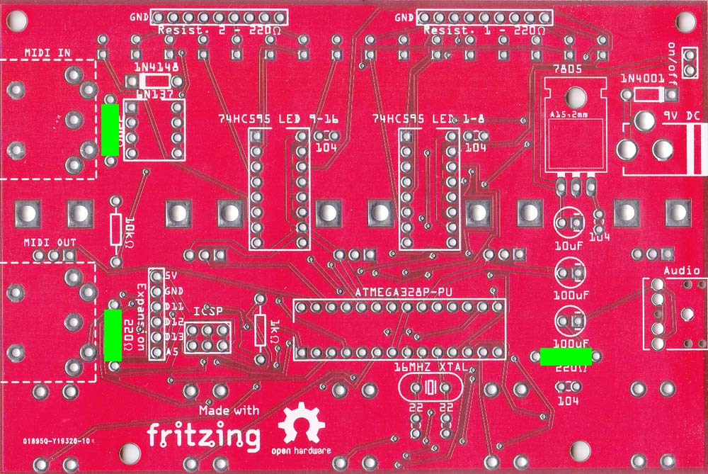
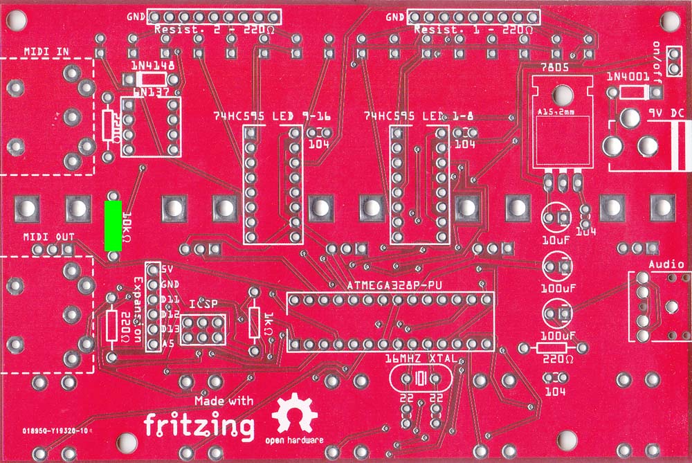
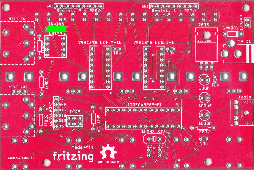
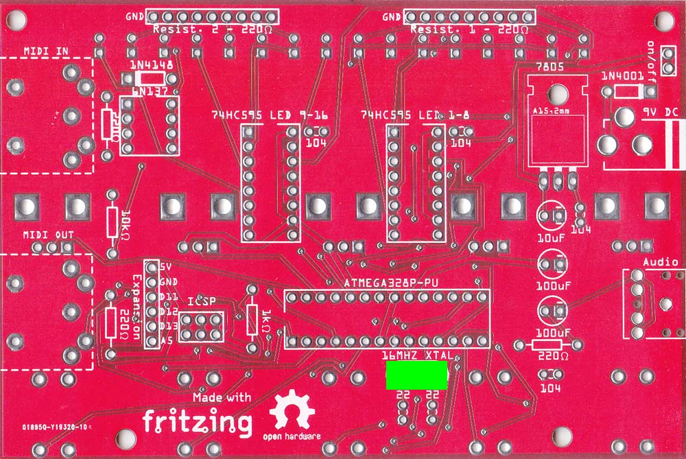
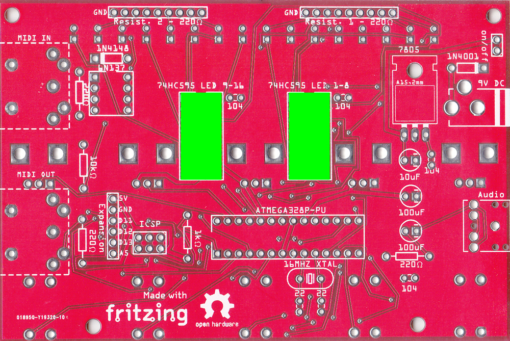
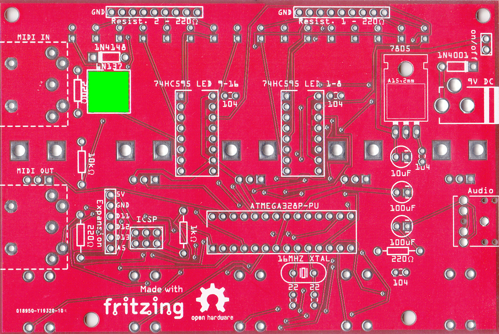
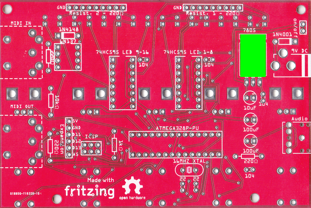
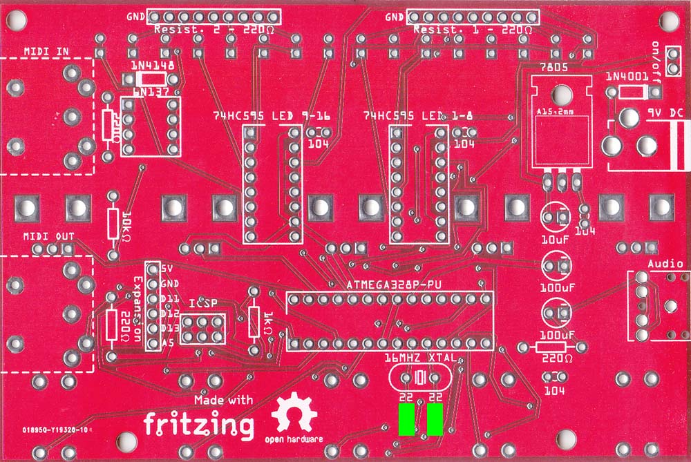
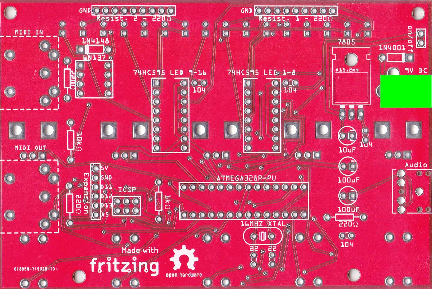
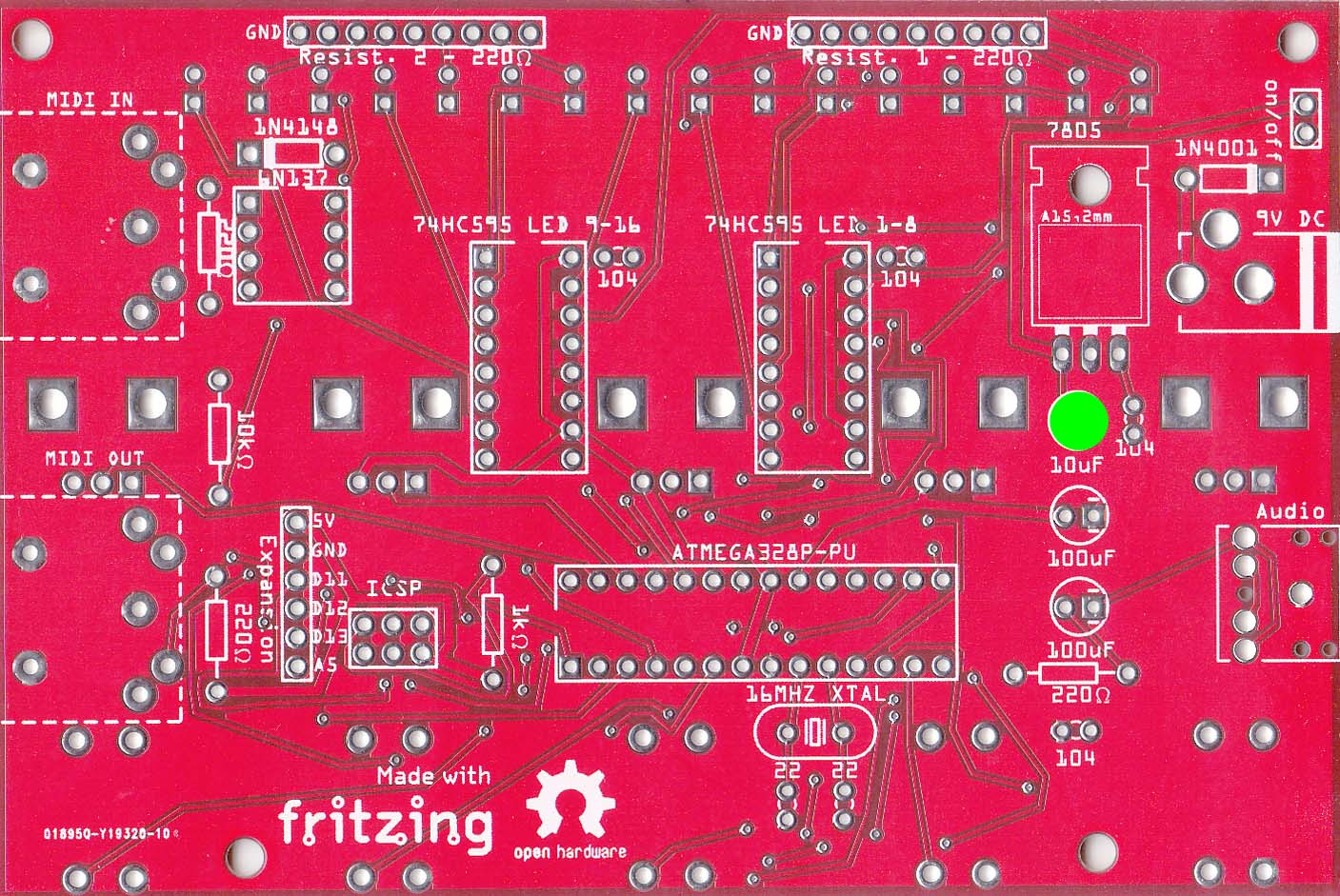
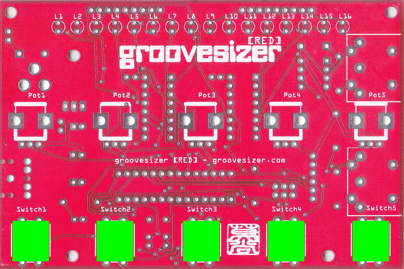
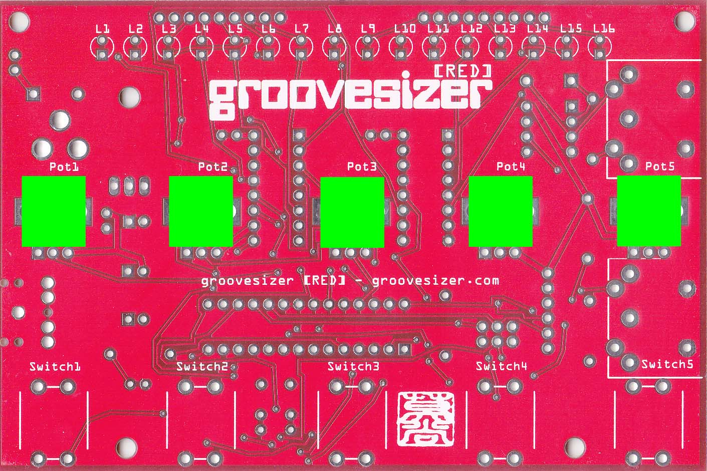
PCB BOTTOM
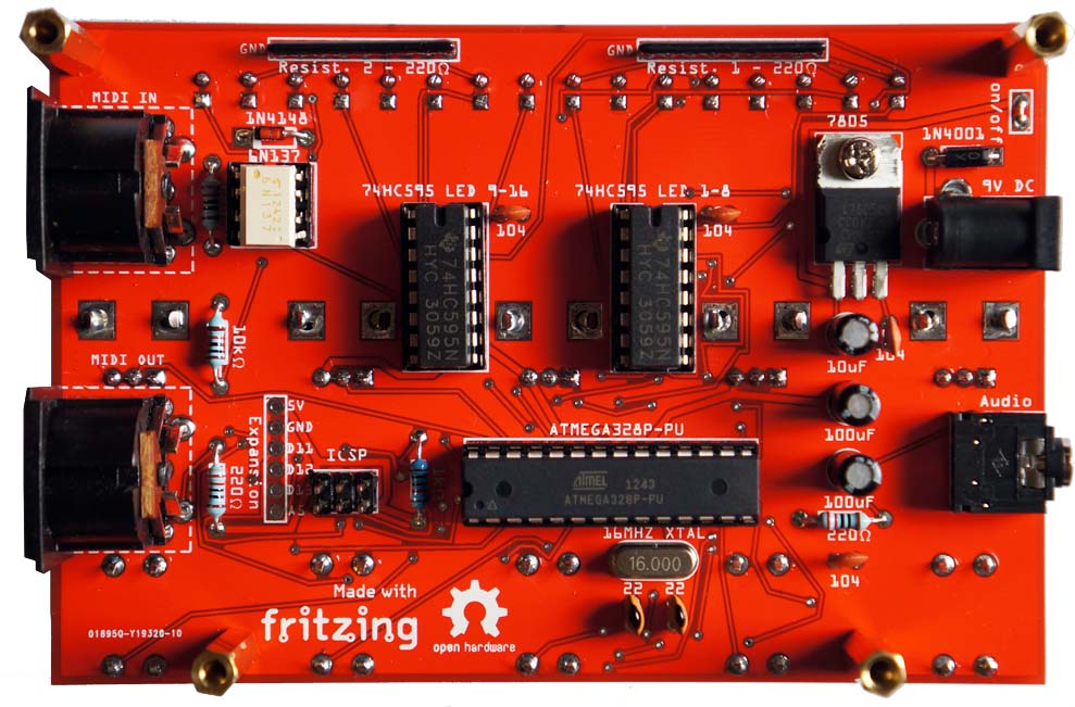
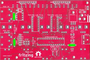
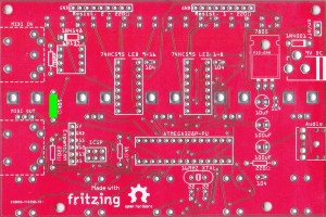
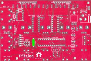
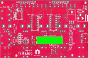
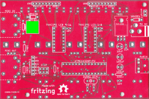
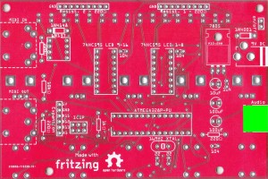
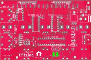
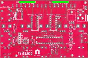
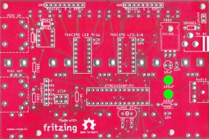
We’ll populate the bottom of the board first – it’s the side with the Fritzing and Open Hardware logos. Here’s a shot of the completed bottom of the board for reference (click on any of the images to enlarge them.)
-
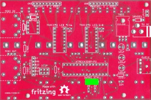
On/Off Jumper We’ll start by soldering in an permanent jumper for the on/off switch.
 If you plan to add a switch later, you can still go ahead and add the bridge now – it’s easy enough to desolder later. (Have a look at the end of these instructions for an example of a switch.)
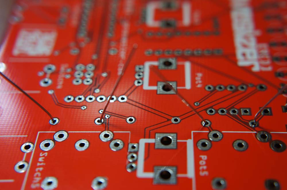
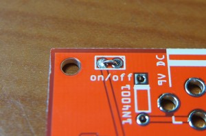 We start here, since it’s an easy step to skip by mistake. It’s also in keeping with our plan to populate the board with components from smallest to tallest – it makes it easier to solder, since you can just flip the board around and the components will stay in place. If you have some solid core wire lying around, use that, or else snip off half (not too much now!) of a leg of one of the resistors.
 Bend it into a U shape and insert it into the board.
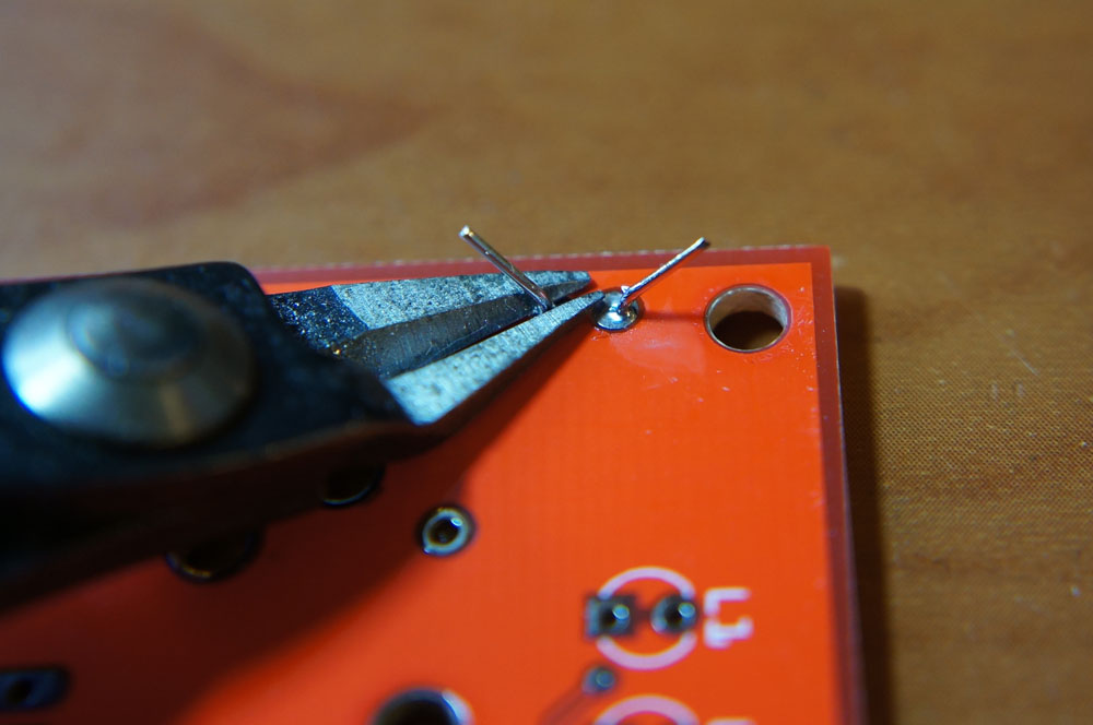
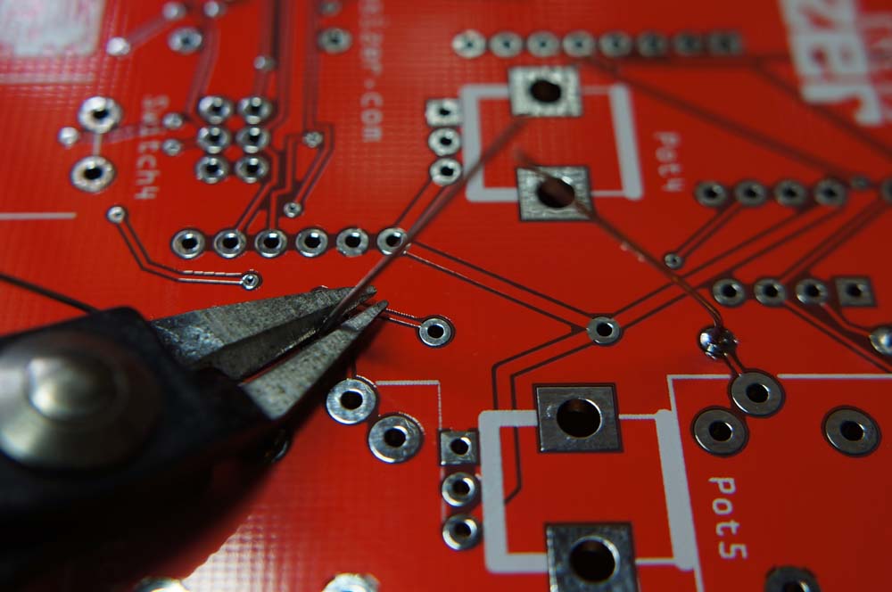
 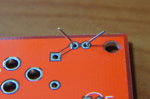 Flip the board over, solder the jumper and snip off the remaining legs with your cutter.
  CAUTION: cutters are sharp and traces are thin, so watch out when you snip that you don’t accidentally scratch through a trace!
 -
Resistors
-
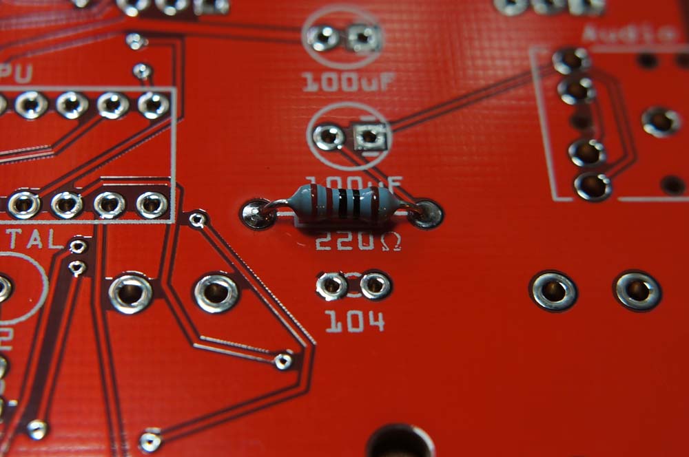
220Ω x 3 (red, red, black, black, brown)
 You’ll need 1 each for the MIDI input and output circuits,
  as well as one for the audio output circuit.
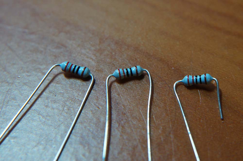
 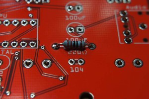 Resistors are not polarized, so it doesn’t matter which way around they go in. Bend the legs into a staple shape,
  and fold the legs over once you’ve inserted them into the board. You don’t need to fold them over too much, it’s just so they don’t fall out when you flip the board over. It’ll make it easier to solder and snip off the legs if you don’t.
  Go ahead and solder once they’re in, then snip off the legs.
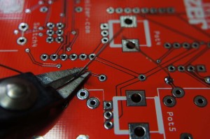
-
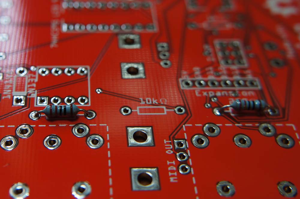
10kΩ (brown, black, black, red, brown)
 This one is also for the MIDI input circuit.
 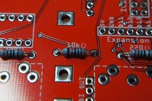 Solder and snip.
 -
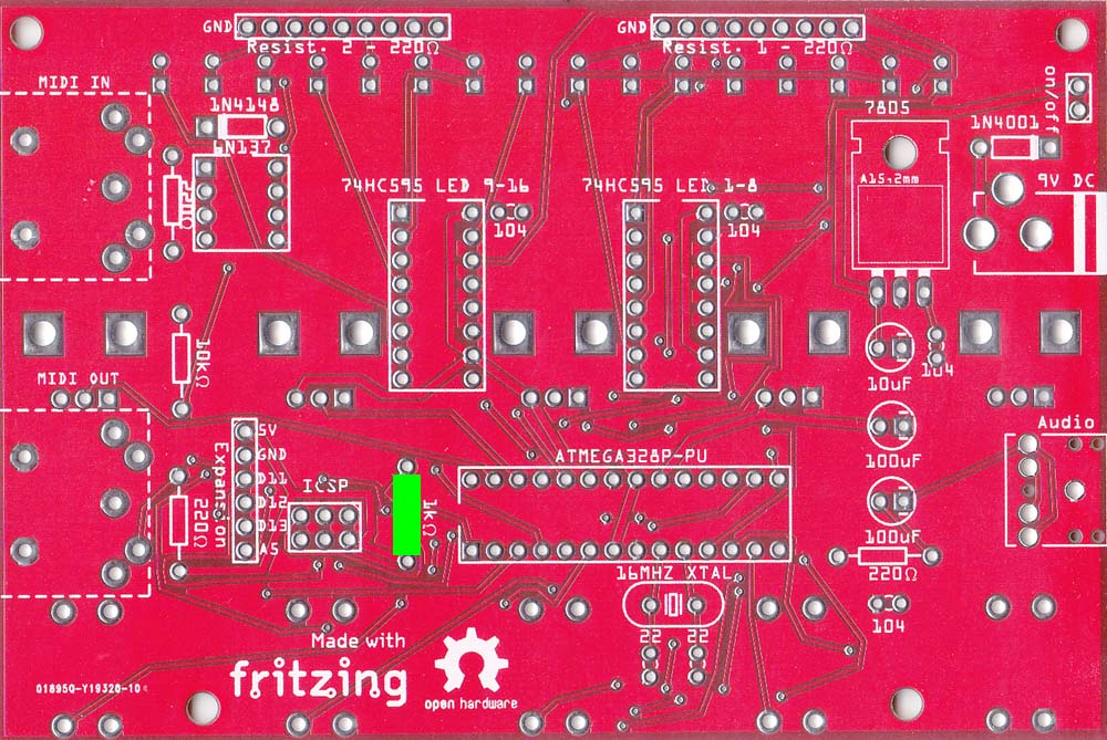
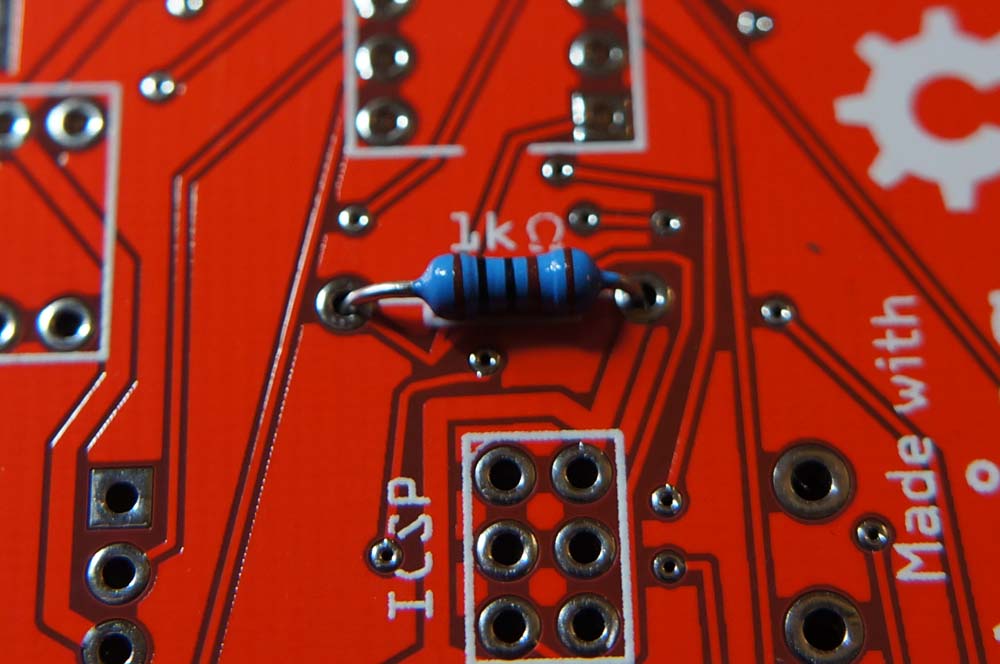
1kΩ (brown, black, black, brown, brown)
 This one is for the ATMEGA’s reset pin.
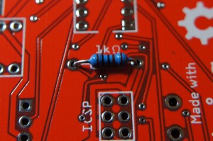
-
-
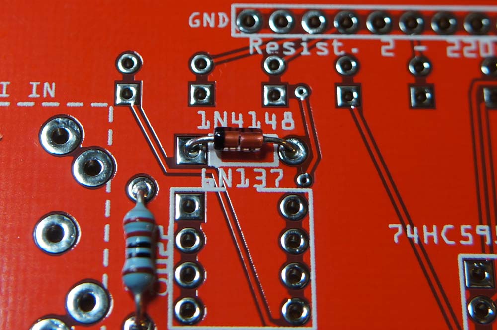
Diodes & XTAL You can add these together, and solder and snip in one go. Watch out, the diodes are polarized, so pay close attention to which side the line marking on the diode body goes – it’s marked with a thicker white line on the PCB.
-
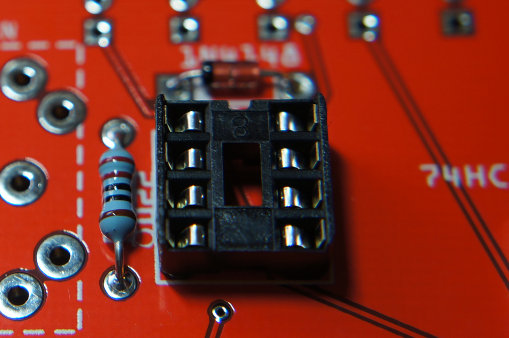
1N4148
 The 1N4148 has the see-through glass body.
  It’s required by the MIDI input circuit.
 -
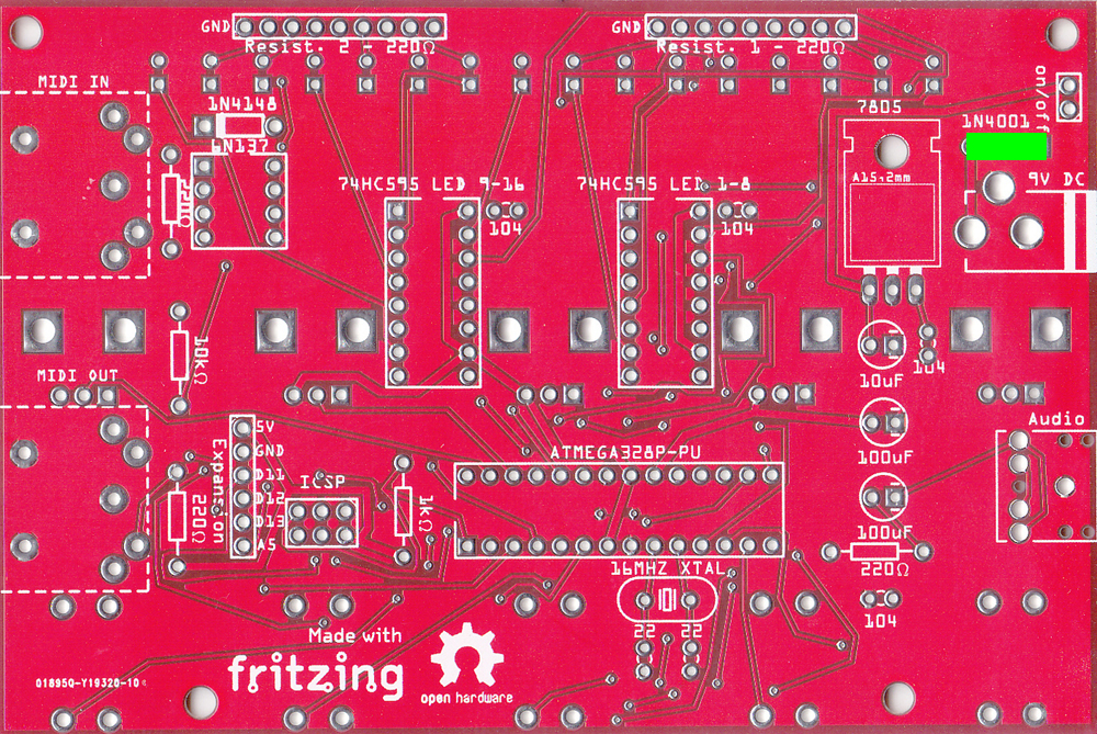
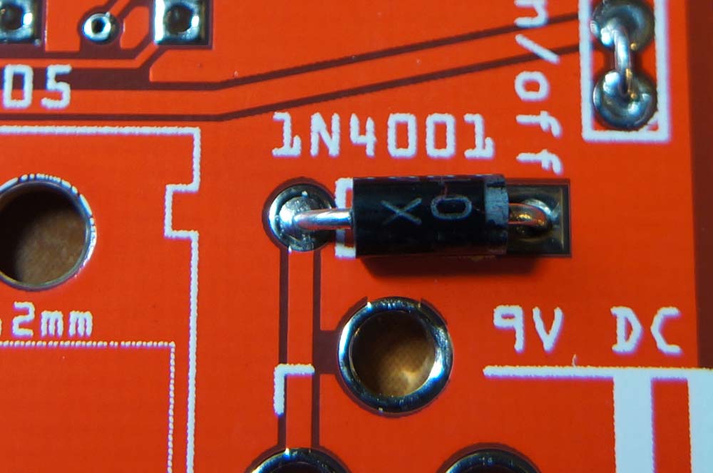
1N4001
 It’s the black one.
  It prevents damage to the components if the board is fed power with reversed polarity.
 -
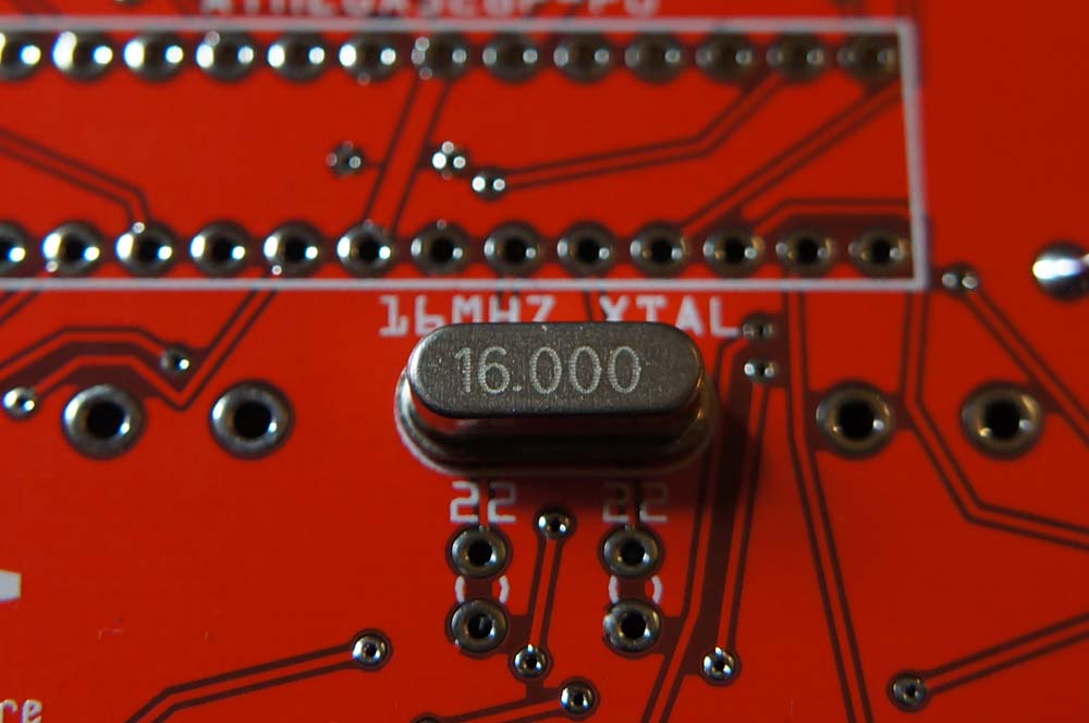
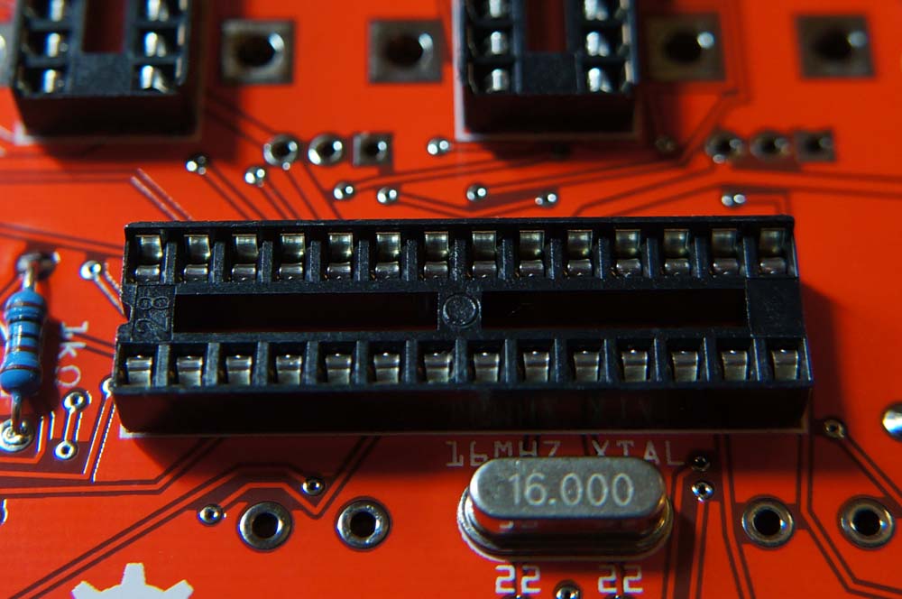
XTAL
 The crystal clock (XTAL) is not polarized, so it can go in either way.
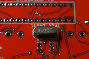 It’s required by the ATMEGA.
-
-
IC Sockets For each of these, the side the notch goes is marked on the board by a broken line on the ICs outline.
-
28 Pin Socket
 It’s for the ATMEGA328P-PU.
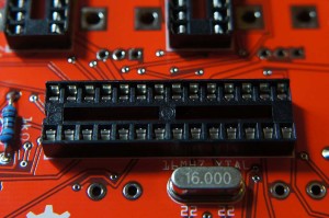
-
16 Pin Socket x 2
 They’re for the two 74HC595 shift registers.
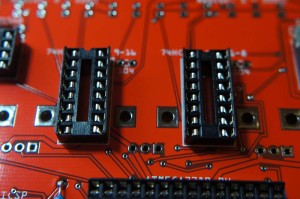
-
8 Pin Socket
 It’s for the 6N137 optocoupler.
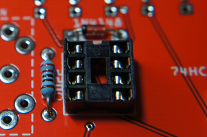
-
-
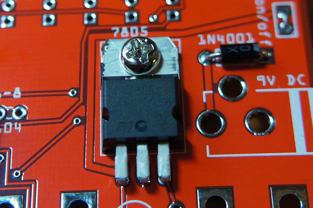
7805 Voltage Regulator
 It’s polarized, but with the legs bent the way they are, there’s really only one way it can go in. It’s not essential, but you can use a screw and nut to secure the 7805 to the board.
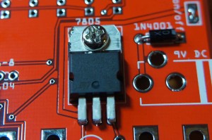 Make sure it’s flat against the board before you solder and snip.
 -
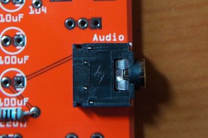
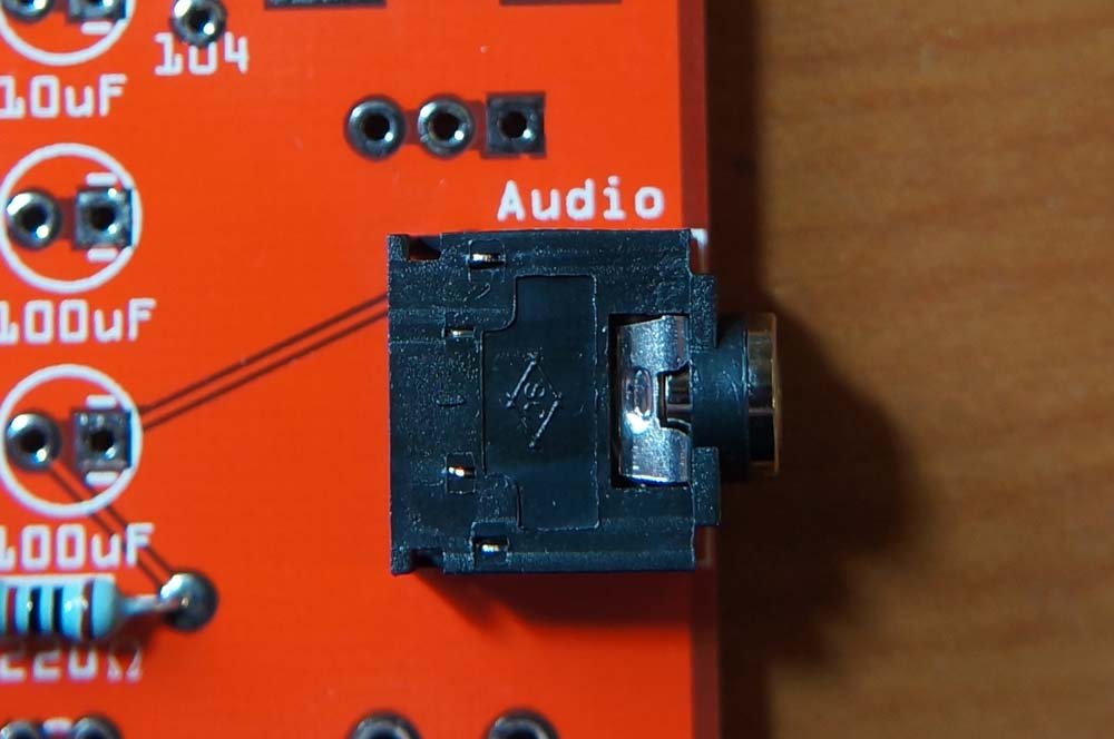
⅛” Mini Jack
-
Ceramic Capacitors These brown ceramic disks are not polarized, so they can go in either way around.
-
104 (0.10uF) Capacitors x 4
 They’re marked “104″.
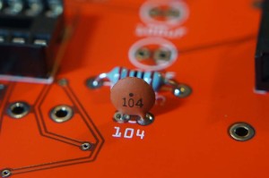
-
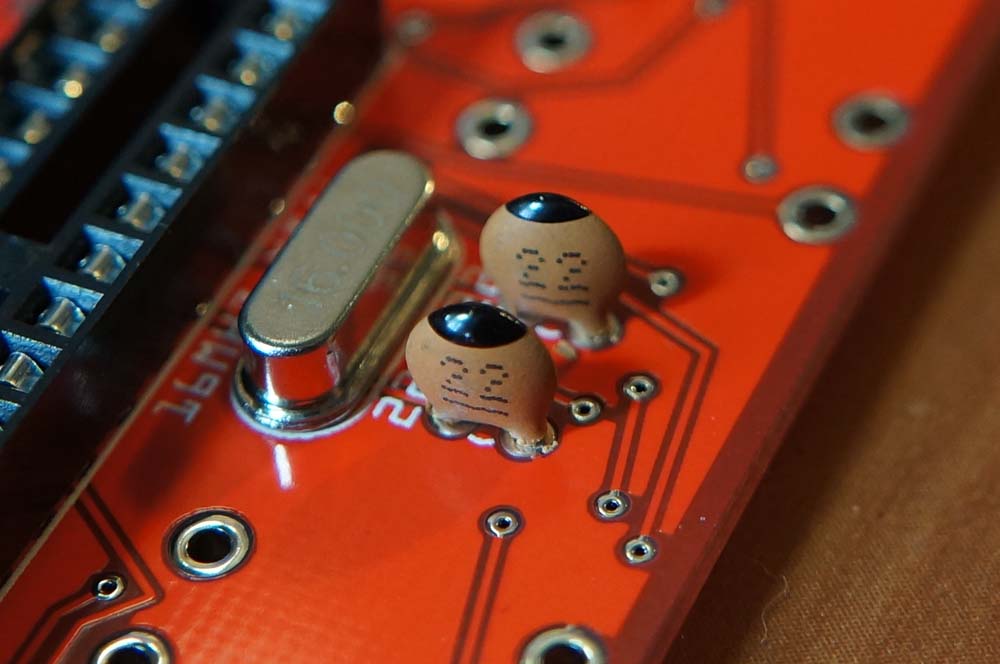
22 (22pf) x 2
 They’re marked “22″ and have black dot on the top rim.
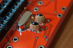
-
-
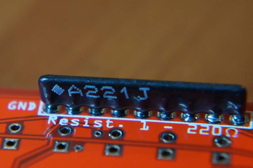
Resistor Networks 220Ω x 2
 The ground pin is marked with a diamond shape on the body and with GND on the board.
  It’s not strictly necessary, but I like to snip off the bits of the legs sticking out on the top side of the board.
 -
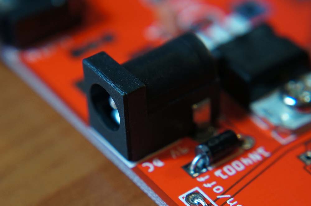
9v DC Power Jack
 You can be generous with the solder and fill the holes, because the jack will see a lot of action and we want a solid connection to the board.
-
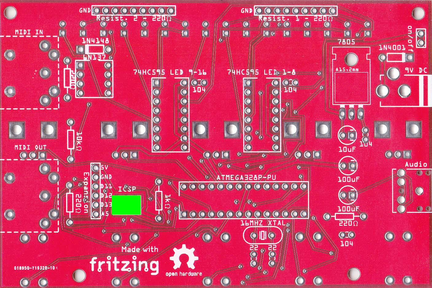
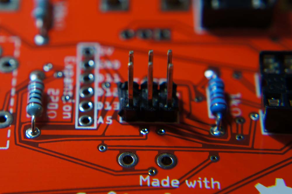
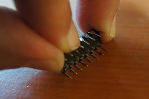
ICSP Header (6 pins)
 Solder – if you got the long kind, you may want to snip off the legs sticking out on the top side of the board.
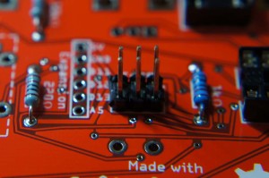 It’s used to program the ATMEGA.
 -
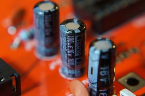
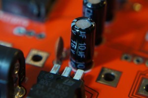
Electrolytic Capacitors Watch out – these are polarized. The white (or gold) line marked with minuses on the side of the cap indicates ground. On the board, the ground side’s pad is square and there are two white lines on either side of it. I usually tack one leg with solder, heat it up and straighten it, then solder the other leg.
-
100uF Capacitors x 2
-
10uF Capacitor

-
-
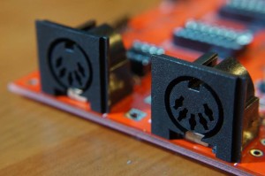
5 Pin DIN Connectors (MIDI In & Out) x 2


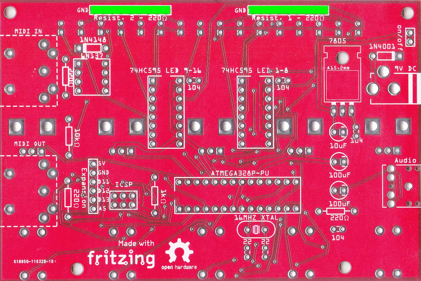


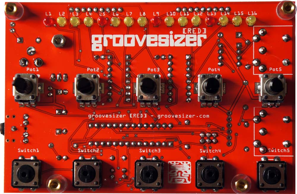
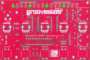
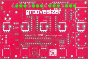
PCB TOP
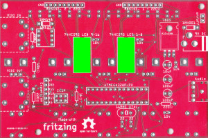
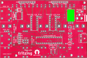
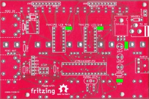
It’s time to flip the board over and add the components for the top of the board. Here’s the completed top of the board for reference.
-
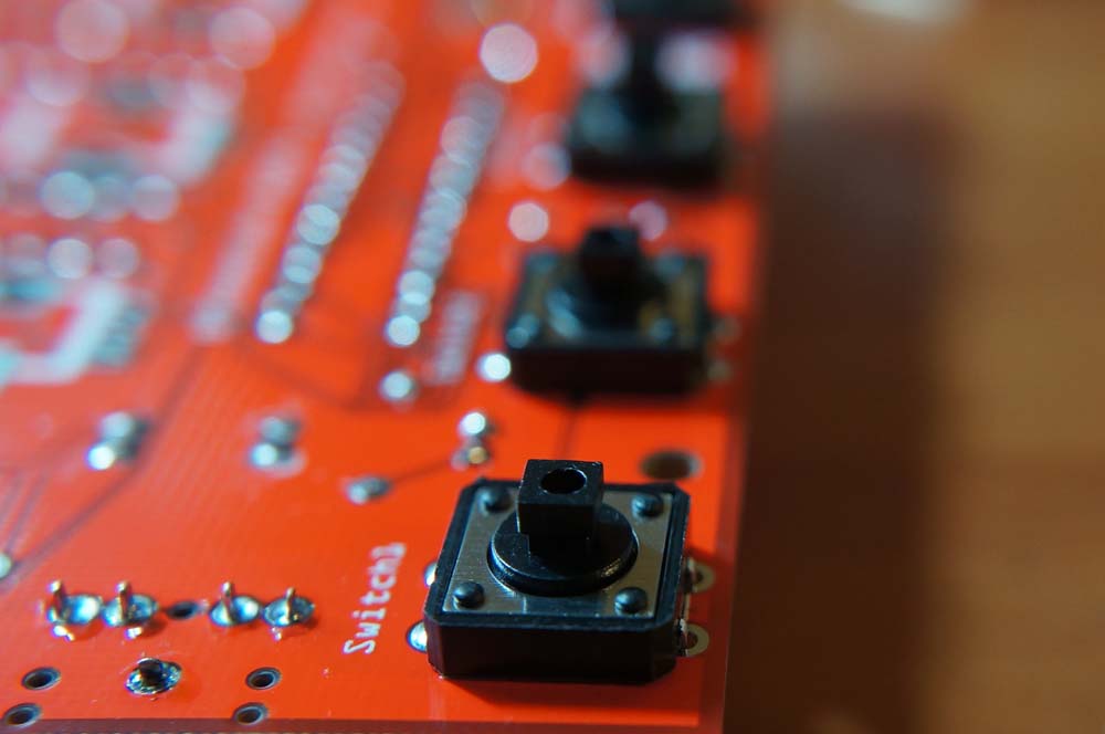
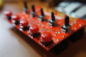
Buttons x 5
 It’s a good idea to only tack one corner and make sure the button is flush with the board before soldering the other legs.
-
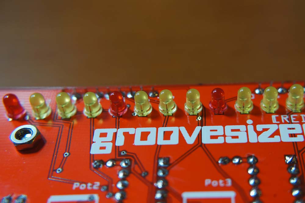
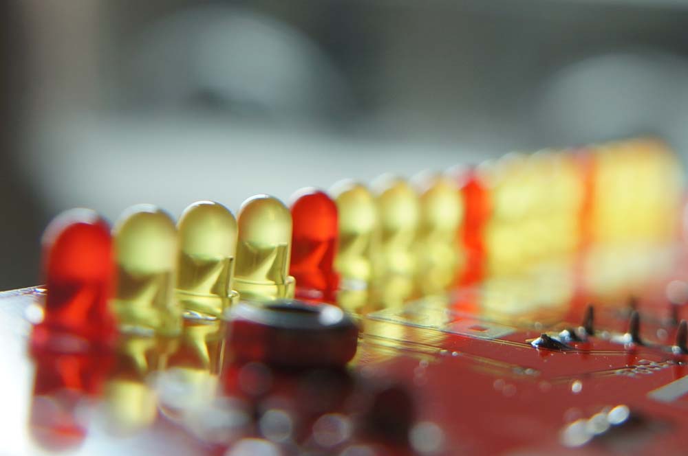
LEDs
 The LEDs are polarized The shorter leg goes towards the top (potentiometer side) of the board. On the board, the pad for the shorter leg is round and the one for the longer leg is square.
 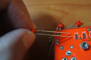 Once they’re all in and before you solder, check the orientation again. You should be able to make out a diagonal line inside the LED – make sure this line runs the same direction for all of the LEDs.
  Again, only solder one leg, make sure it’s straight, then solder the other leg.
-
Red x 4
 The red LEDs are for L1, L5, L9 and L13.
 -
Yellow x 12
-
-
10k Linear Potentiometers x 5
 Snap them in and solder. Just make sure they’re straight.
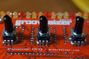


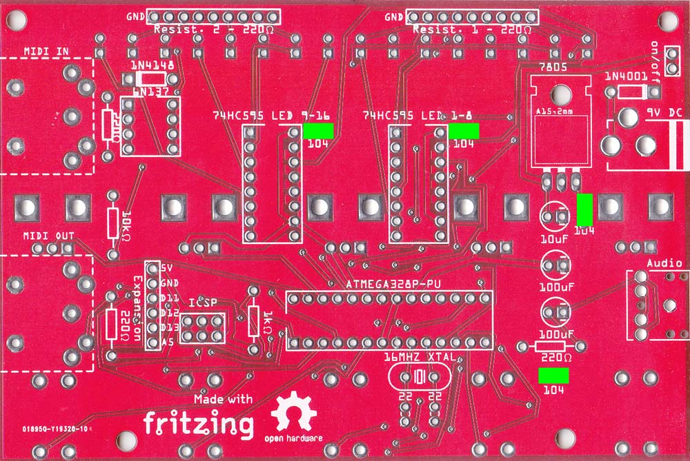
PCB BOTTOM
-
Seat your ICs. You’ll probably have to bend the legs in a little – bend them all together by rolling the IC on a flat surface.
 Take care with the orientation when seating the ICs – be sure to refer to the shots below.
-
74HC595 x 2
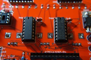 These control the 16 LEDs.
 -
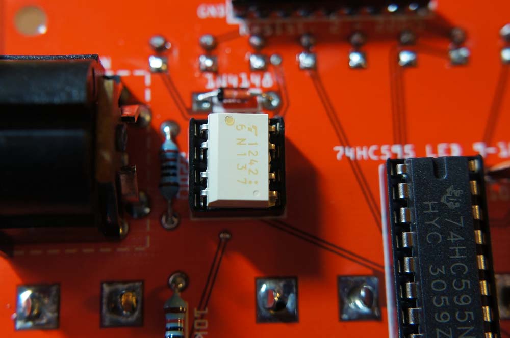
6N137
 It’s used by the MIDI input circuit. The beveled edge faces the MIDI input socket
 -
ATMEGA328P-PU
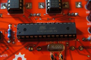 This is the brains of the operation.
-
-
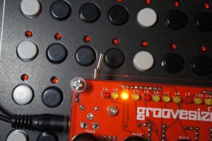
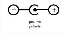
Test your build! Plug in a 9v power adapter with 2.1mm barrel and center pin positive. They’re usually marked like so:
 Your Groovesizer should jump to life right away – if it does, congratulate yourself with an evil genius “Mhwuhahahaha!” If there’s a hitch, refer to the troubleshooting page.


HOUSING PLATES, KNOBS AND BUTTONS
NOTE: Be careful when you open the bag with the mounting hardware that you don’t lose some of the nylon washers – the kit only comes withthe 16 you need, but they’re staticky and tend to cling to the other components.
-
Snap on the button caps.
-
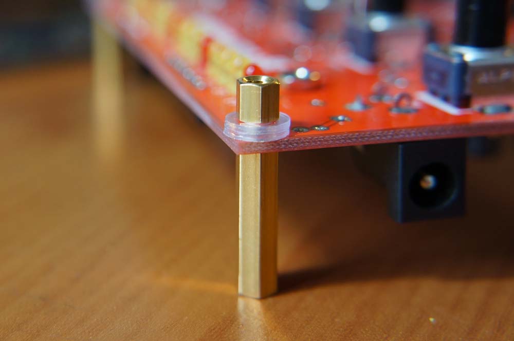
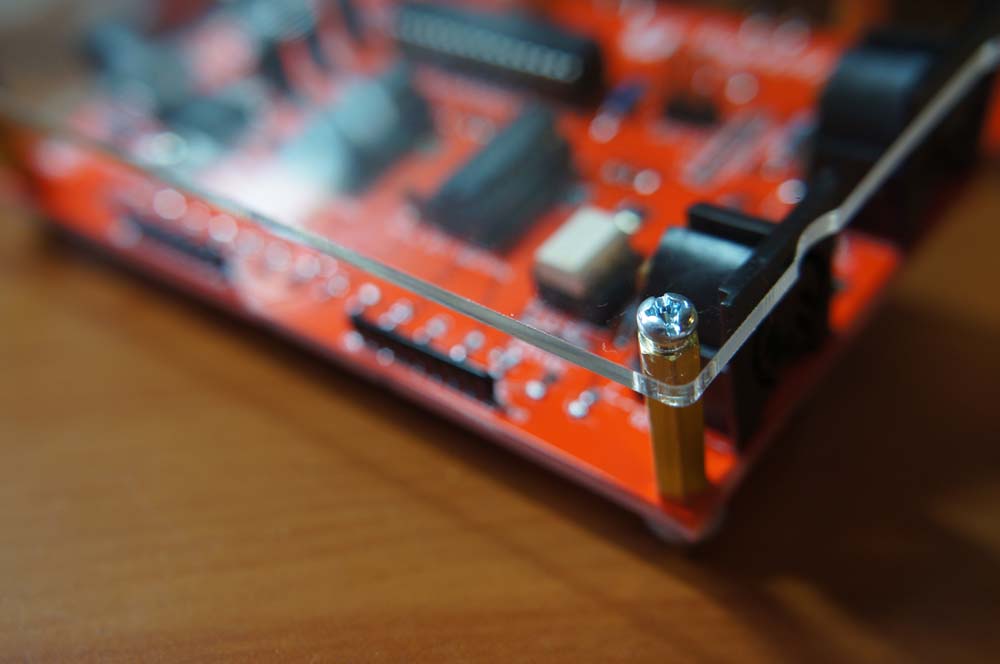
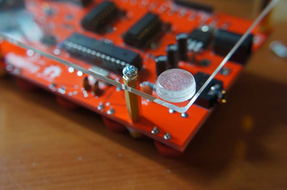
Screw in the hex spacers.
 The 20mm ones are for the bottom and the 4mm ones for the top. Add two washers for each of the 4mm spacers between the PCB and the spacer.
 -
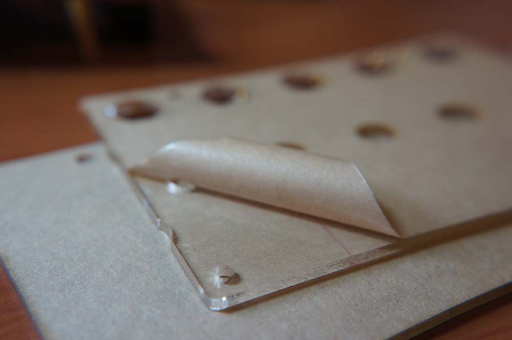
Peel off the protective paper layer from the housing plates.

-
Screw in the bottom plate.
 There are no washers for the buttom plate. I haven’t cracked a plate yet, but I’m sure you can if you screw them on too tightly. The side with the notches is under the MIDI dins. The notch and the bump serve to indicate MIDI input and output.
 -
Stick on the bumper feet.
 Make sure you get the front feet as close to the edge as possible – too far back and the unit will want to tip over when you press the buttons.
 -
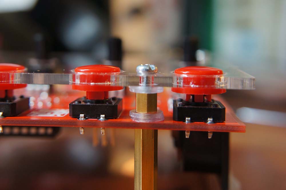
Screw in the top plate with two washers between the spacer and the plate.
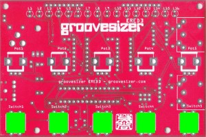
 The buttons don’t stick out by much, but it’s enough to press them. For the sake of clarity, here’s a diagram.
-
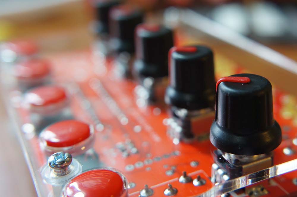
Push the knobs onto the potentiometer shafts.
 If you push them down too far they’ll rub against the plate – not so nice.
 -
You’re all done!

QUICK START
Here’s a quick start vid. Easily check your build before reading the manual (but do read it!).
http://youtu.be/ldW6_QT6ZM8
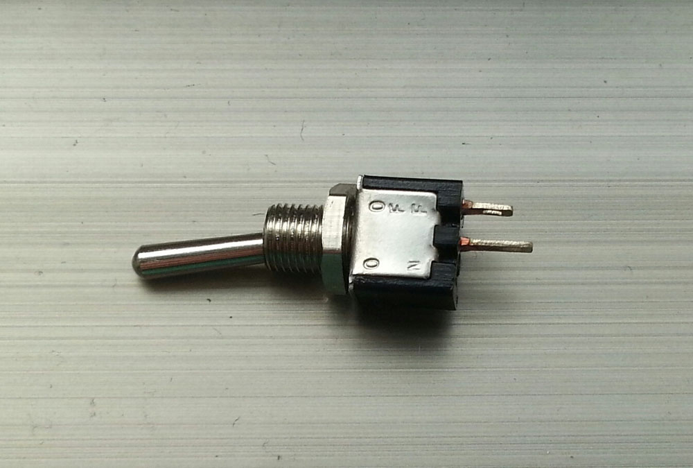
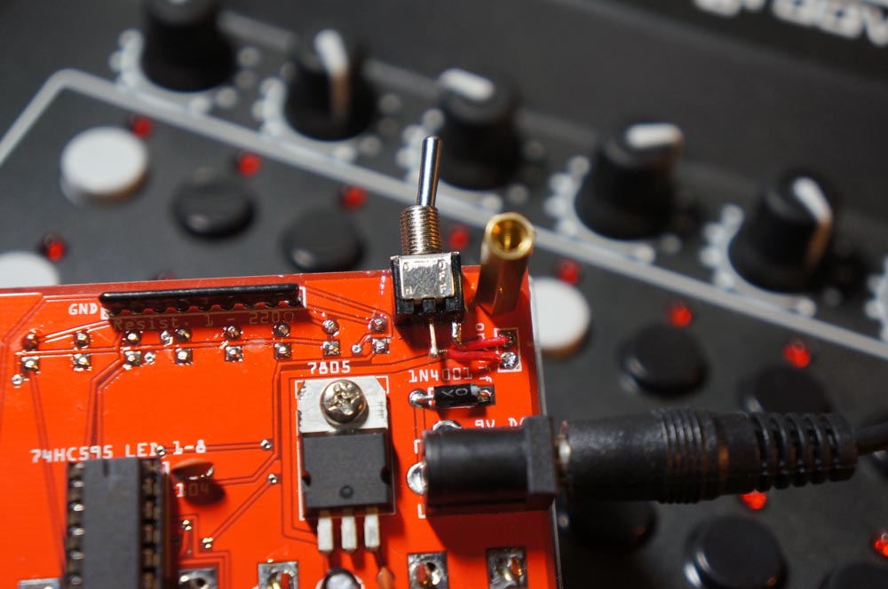
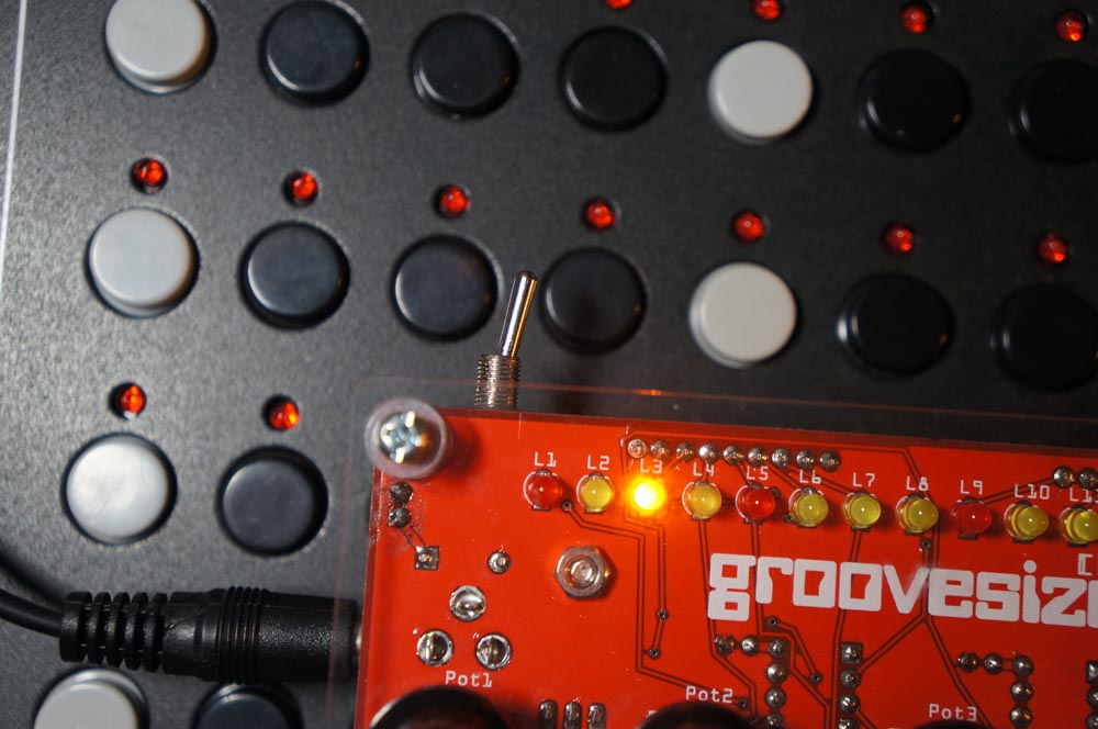
ON/OFF SWITCH (Optional)
There is no switch supplied with the kit, but you can install one if you like. Some people question the usefulness of an on/off switch – the switch will turn the RED on or off, but the 9V DC power supply will continue to use power if it’s plugged into the wall outlet. But that’s the case with all gear with external PSUs. Either way, there may be times when having a switch on the instrument is useful. Anything will do, but I had one of these small toggle switches lying around.
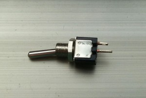 I used epoxy glue to attach it to the PCB and soldered wires to the two pads on the PCB.
 It sticks out quite a bit, but it looks pretty neat.