Please note, these instructions are for the first version of the multiboard.  Instructions for the current board are here.
For a beginner, this is not the quickest of builds, but there’s really nothing tricky about it either since the board uses through-hole components exclusively and all the components are on the same side of the board. If you’ve never soldered through-hole electronics before, I suggest you give yourself a quick primer with one of the numerous through-hole soldering tutorials on YouTube, like this one.
Importantly, take all the time you need – there’s no rush. And work in a well-ventilated space.
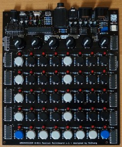
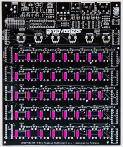
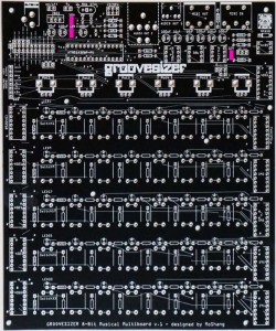
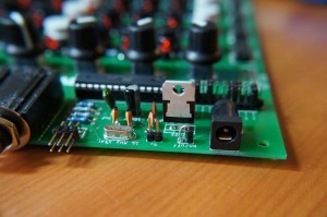
Here’s a completed board for reference (click on the images to enlarge them).
1. 220Ω resistors x 42 (red, red, black, black, brown). You’ll need 1 for each LED, 1 for the MIDI input circuit, and 1 for the MIDI ouput circuit.
Resistors are not polarized, so it doesn’t matter which way around they go in – that said, if you insert them all in the same orientation it’s much easier to spot a mistake.
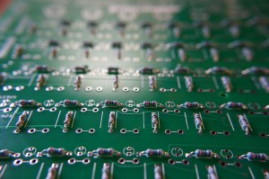
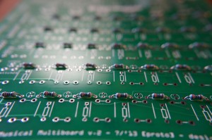 Bend the legs into a staple shape,
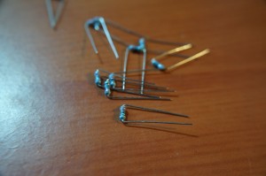 and fold the legs over once you’ve inserted them into the board.
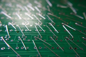 Go ahead and solder once they’re all in, then snip off the legs.
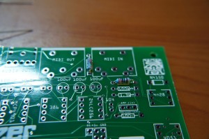
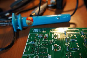
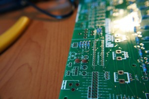
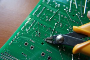 CAUTION: cutters are sharp and traces are thin, so watch out when you snip! Yikes, I’ve managed to cut through a trace on this board. (Don’t rush it remember?)
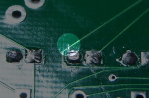 If you suspect you’ve done it, check with your multimeter. All’s not lost if you have – just run a wire to bypass the break in the trace. But it’s certainly annoying!
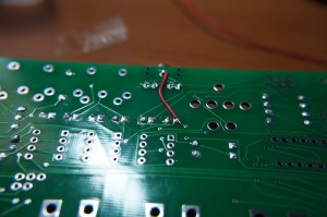 How was that? Ready to do it again?
2. 10kΩ resistors x 40 (brown. black, black, red, brown). There’s one for each tactile switch.
Add them as above, solder, and snip. Now add:
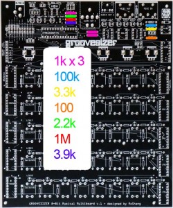
3. 1kΩ resistors x 3 (brown, black, black, brown, brown)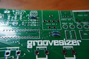
4. 100kΩ resistor x 1 (brown, orange, black, black, brown)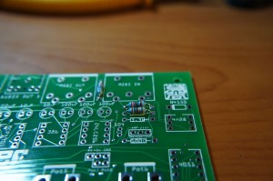
5. 3.3kΩ resistor x 1 (orange, orange, black, brown, brown)
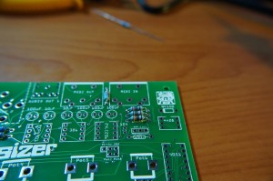
6. 100Ω resistor x 1 (brown, black, black, black, brown)
7. 2.2kΩ resistor x 1 (red, red, black, brown, brown)
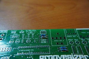
8. 1MΩ resistor x 1 (brown, black, black, yellow, brown)
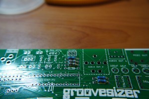 9. 3.9kΩ resistor x 1 (orange, white, black, brown, brown).
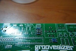 Then solder these 9 suckers and snip. You’re done with the resistance, on to the caps. Add the following:
10. 104 (0.10uF) capacitors x 3 (not polarized) – they’re brown ceramic disks marked “104”.
11. 22 (22pf) capacitors x 2 (not polarized) – also ceramic disks marked “22”.
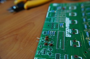
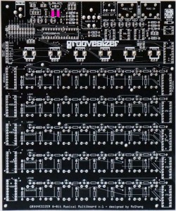
12. 4.7nF capacitor x 1 (the green one – not polarized)
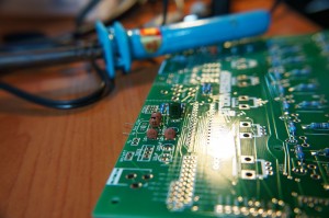
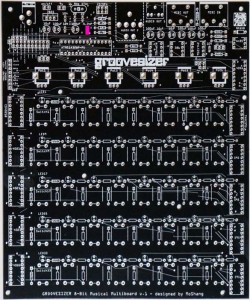
13. 100uF capacitors x 6. Watch out – these are polarized.
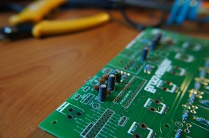 The white line on the side of the cap is ground and should face to the left-hand side of the board.
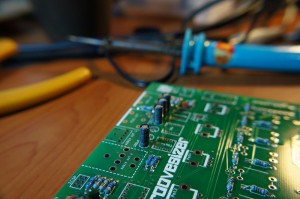 The ground side’s pad is square and there are two white line on either side of it.
14. 10uF capacitors x 3. Same thing – polarized!
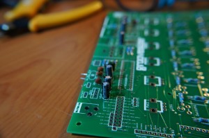
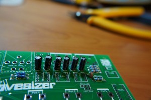 And let’s also add the diode:
15. 1N4148 diode (it’s the see-through one).
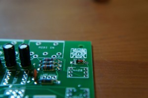 It’s also polarized. The black line is on the left-hand side of the board. There’s a thicker white line to indicate it (under the “N” of the N4148 marking). Solder all and snip! Next up we’ll add the:
16. 9v DC Power Jack.
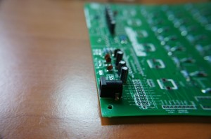 You can be generous with the solder and fill the holes, because the jack will see a lot of action and we want a solid connection to the board.
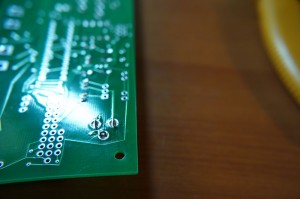 No need to snip the legs. Then, add the crystal:
17. 16MHz Xtal (crystal). Solder and snip before you add the voltage regulator:
18. 7805 voltage regulator.
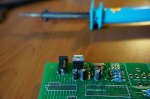 It’s polarized! If it were a chair, the seat would face towards the inside of the board. Then, let’s add the small audio jack:
19. ⅛” Mini Jack.
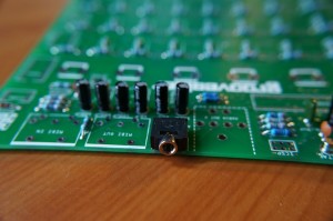 Solder, but no need to snip. Same deal with the large audio connector:
20. ¼” Jack.
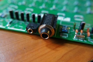 Solder, no snip. Next up, we’ll add the MIDI connectors:
21. 5 Pin DIN connectors x 2.
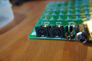 Still some things left to do at the top of the board, but we’ll come back to them a bit later. Next, we’ll add the pots:
22. 10k Linear Potentiometers x 6.
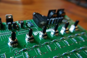 Snap them in and solder – no need to snip. Time for a small marathon again. Let’s add the buttons:
23. 12mm Tactile Switches x 40.
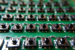 They can go in either way, but just make sure they’re flush against the board before you solder (no snip). Hey, that wasn’t so bad, was it? It’s starting to look like a Groovesizer now. Let’s add some headers and jumpers:
24. ICSP header (6 pins).
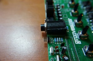 This one is L-shaped to allow access once the Groovesizer is in its enclosure.
25. 9v header (2 pins).
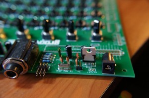 Add a jumper-header here, so you can turn off power to the 386 amp when not in use.
26. 1N4001 protection diode (the black one).
The protection diode was left out as an oversight – it’s not strictly necessary for the Groovesizer to work, but man, you’ll be glad it’s there the day you borrow a friend’s power supply and DON’T fry the components because of swapped polarity.
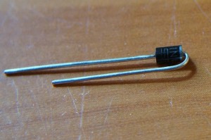 Bend the positive leg over 180 degrees (the positive end of the diode is marked with a while line).
The protection diode goes next to the next to the 9v power jack on the spot originally intended for an optional on/off switch. The body of the diode goes closest to the power jack (the side marked with “on”), and the folded over leg goes on the side marked “off”. Next up, the options jumper headers:
27. Options header (11 pins, 10 pins, 4 pins).
Break off the required lengths of pins from the long single row header. Use the jumpers to anchor the single rows together (see the photo)
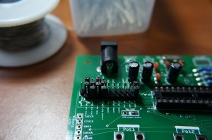 and solder them to the board. To set up the jumpers for your firmware, refer to the manual of your firmware. For the Alpha firmware, see here.
28. Volume. I’m adding a permanent jumper between the audio and wiper pads (using a snipped off leg from one of the other components), but you can add a volume pot if you’re so inclined (10k audio/logarithmic – not included).
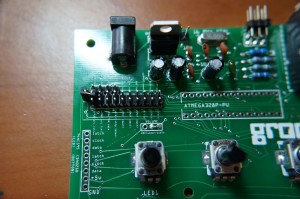 Solder – snip! We’ll add the socket for the microcontroller next:
29. DIP socket (28 pins) x 1.
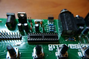 The side with the notch goes on the left. And three 8 pin sockets for the the DAC, the amp, and the EEPROM:
30. DIP sockets (8 pins) x 3.
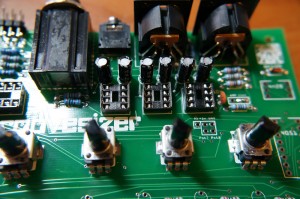 The notches go at the top. Now, let’s at some ICs – we’re not going to use sockets for them, instead soldering them straight to the board:
31. Amp input trimmer.
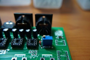 Insert (either way is fine), solder, and snip.
32. IC 4n35 optocoupler x 1.
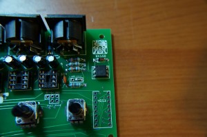 Mind the orientation – the dot that marks the 1st pin goes top left. The one pictured is a 4n28, but that didn’t work out so we’ll be going with 4n35. We’ll add the multiplexers next, starting with the single:
33. IC 4051 x 1.
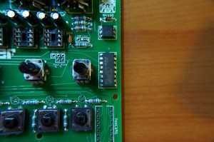 The notch goes at the top. Next up, 5 595s:
34. IC 74HC595 x 5.
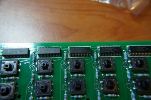 Again, the notches go at the top. And then add the 4021s:
35. IC CD4021B x 5.
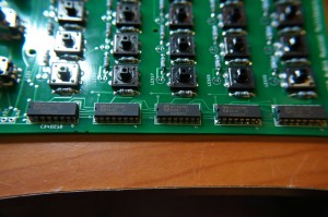 Actually, these Philips chips are HEF4021BP, but it’s the same thing. Notches at the top. Once they’re soldered, take a small break, because we’re about to do our last soldering – unfortunately, it’s another marathon.
36. LEDs x 40 on holders x 40. I know you’re supposed to put the LEDs in the panel-mount holders, but we’re just using them to raise the LEDs off the board like so…
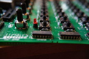 Make sure you get the orientation right! The shorter leg goes towards the top (potentiometer side). This means that the larger triangle inside the LED (the thing that look’s like a shark’s fin) is towards the bottom of the board. Add them all, and check the orientation of each LED again.
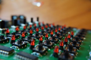 Top tip: when soldering the LEDs, first tack one leg, make sure the LED’s straight, and then fix the position by soldering the other leg.
37. Socket the four ICs. Take care with the orientation. Refer to the photo if you’re unsure. 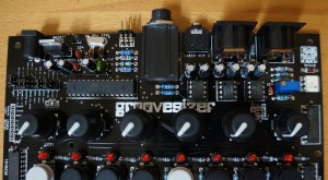
37. Push on the plastic knobs of the potentiometers, and snap on the button caps for the tactile switches. You’re all done!
