Intro
If you want to cut straight to the chase, skip to Part A below.
Just some quick info regarding the basic parts of an Arduino sketch in my own words. A program written in C or C++ (both are used in the Arduino IDE) is most often a collection of functions that give instructions to the processor. Functions in turn, are collections of individual instructions and other function calls. Instead of calling out a bunch of instructions again and again, we bundle them together as functions.
A real-life example would be me telling my toddler to “brush your teeth”. He already knows “brush your teeth” is a collection of the following instructions:
- take your tootbrush
- put toothpaste on it
- put the brush + toothpaste in your mouth
- wriggle it around as if brushing your teeth
- take a sip of water
- rinse your mouth
- spit out the water
- rinse your toothbrush
- put the toothbrush away
So (usually), I can just say “brush your teeth” and I don’t have to repeat each individual instruction.
Using functions makes the code neater and easier to read. It also means that if you change something in the definition of the function, you automatically make the change for each instance where the function is called (so you don’t have to change each function call individually). Here’s one of many tutorials on C functions available on the web.
For an Arduino sketch to compile (the process where the human readable code is turned into machine code), you need to define at least the two functions called setup() and loop() (see Bare Minimum on the Arduino website.)
Before we get to these functions, however, we will usually have code to include any libraries we want to use, and to declare our global variables. Global variables are variables that we want to be able to use in any of our functions. If we declare a variable inside of a function definition, we generally limit its scope to that function only) – more on that later.
void setup()
{
}
The name of this function is setup. The void bit at the front means this function won’t return anything (it will just do stuff, not give us an “answer”). The () round brackets are empty, because this function doesn’t take any arguments. Our actual setup code will go between the curly braces {}. As the name implies, setup code runs only once when the program starts (ie. when the device is switched on).
void loop() { }
This will be the main body of our sketch. Again, the function called loop returns nothing and takes no arguments. The code between the curly braces will run repeatedly from top to bottom – when it reaches the bottom, it jumps back to the top. Provided you haven’t written in any delays (and your code doesn’t crash!), the code in the loop will run many many times a second for as long as the device is powered.
Controlling LEDs on the Arduino
Controlling LEDs on an Arduino board is really simple, and it’s the first thing they teach you to do (see Blink). Basically, you connect an LED to one of the Arduino’s digital ouput pins (don’t forget a current limiting resistor so you don’t blow it). First, you set the pin mode to output (you want to turn in on and off, not check to see whether it on or off) with this line of code in the setup function.
pinMode(13, OUTPUT);
The 13 above is the number of the digital pin (the Arduino Uno has 14 digital pins, numbered 0 to 13) – often the pin number will be given a name by defining it as a constant variable.
Then you can turn the LED on by taking the pin high (+5v on the Uno), or off by taking it low (ground) with digitalWrite(). To take it high, you can use
digitalWrite(13, HIGH);
or
digitalWrite(13, 1);
And to take it low you can use
digitalWrite(13, LOW);
or
digitalWrite(13, 0);
Groovesizer and the 40 LEDs
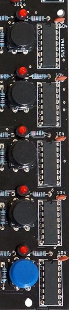
On the Groovesizer unfortunately, things aren’t quite as straight-forward. We need to control 40 LEDs and, as mentioned, we only have 14 digital ouput pins on the ATMEGA328P-PU processor at the heart of the Arduino UNO and the Groovesizer MB. To extend our output capabilities, we need to call on the help 74HC595 shift register ICs. Since we’re about to get friendly with them, we can call them 595s for short. There are 5 of them (one for each of the LED rows) mounted on the right hand side of the MB.
The 595s have a couple of super powers that make them perfect for our use. Each 595 has 8 digital output pins, but you only need 3 of the ATMEGA’s digital pins to control them. Furthermore, they can be daisy-chained – with just 5 of them we can control our 40 LEDs, all for the low-low cost of 3 ATMEGA pins. You can read all about how the 595s work their magic here, but here’s a short description. The three ATMEGA pins we use to control the 595s are called latch, clock and data. We prepare the 595s to receive data by taking the latch pin low (and well keep it low as long as we’re sending data). Next we pulse a series of on and off messages to the 595s. The clock pin advances the registers on the 595s to receive the next bit – each bit tells the appropriate 595 whether a particular output pin is high or low (ie. whether the LED is on or not). When we’re done, we take the latch pin high again.
To make communicating with the 595s easier, we use the shiftOut() function. Previously, I’ve included the definition of the shiftOut() function in the firmware code – basically because I didn’t realize a definition of shiftOut() is already baked into the Arduino IDE. From now on we’ll just use the included one. If you want to see how our earlier version of shiftOut() is implemented, you can look in the HelperFunctions tab of the current Delta and Alpha firmware.
Before we get to the actual code example, just a quick note on comments. Comments are meant for a human reader – to tell the compiler to ignore comments, we mark them with // or /*…*/, for example
// this is a comment
or
/*
This is a comment with more than one line.
Like this one.
And this one.
And this one.
*/
Part A
Download the following code example: Tutorial_MB001_A
The code starts with some comments about the file and the license. Then we get down to business defining the three pins we’ll use for the 595s’ clock, latch and data. We define them as const (constant), because they will never change elsewhere in the code. The byte type can hold a value up to 256, so that’s more than enough for a pin number (every byte counts on the ATMEGA328, so don’t use an int (2 bytes) where a byte will be enough).
// the three pins needed to talk to the 74HC595 shift registers
// as for the Alpha firmware
const byte LEDlatchPin = 2;
const byte LEDclockPin = 3; // change the 3 to a 6 for the Delta firmware jumper setup
const byte LEDdataPin = 4;
There’s a comment to change the LEDclockPin’s definition from 3 to 6 if you currently have the MB set up to run the Delta firmware. I’m assuming you don’t want to open the case, just to run the tutorial. It’s not necessary here, though it might become necessary further down the line.
Next, we define an array of 5 bytes to hold the data for the LED rows. Just so it’s clear – a byte consists of 8 bits. We can use each bit to store the on/off state of a LED in a row (8 LEDs to a row). There are 5 rows, so we’ll need 5 bytes.
byte LEDrow[5];
In previous versions, I didn’t have these bytes in an array, instead they were LEDrow1 to LEDrow5. Putting them in an array, however, allows us to optimize the code. As you’ll see just now, we can iterate over the LED array using a for loop to turn them all off, for example.
Next up is our setup function.
void setup()
{
// set the pin mode for the shift register control pins
pinMode(LEDlatchPin, OUTPUT);
pinMode(LEDclockPin, OUTPUT);
pinMode(LEDdataPin, OUTPUT);
}
We set the pin mode for each of out 595s’ pins to output, since we’ll only be sending data to them. When we get to the next tutorial about reading the buttons, you’ll see that we need an input pin to read the button states from out 4021 shift registers.
The setup function is followed by the loop.
void loop()
{
  clearLEDs(); // a function to clear the temporary LEDrow bytes
At the top of the loop, we call a new function called clearLEDs(). The clearLeds() function is defined just under the loop and looks like this:
void clearLEDs()
{
  for (byte i = 0; i < 5; i++) // if there's only one line in the for-loop, we don't have to use curly braces {}
    LEDrow[i] = 0; // 0 in this case is the same as B00000000, ie. all bits/LEDs off
}
We clear our LEDrow bytes by setting them all to zero in a for loop (If you’ve never dealt with for loops before, it’s a good idea to get to know them well now. We’ll be using loads of them, so let me Google that for you). There’s a note that 0 is the same as B00000000 (0 in binary – if you don’t believe me, have a quick look over here).
Back to the loop. Keep in mind that calling the clearLEDs() function doesn’t actually turn off the LEDs, since the actual switching on and off is only done when we call the updateLEDs() function (see below). It just sets the LEDrow bytes to zero, and gives us a clean slate. The reason I like to clear the LEDrow bytes at the start of the loop is because (through trial and error) it seems to be the easiest way to keep track of their on/off states. It saves us the double process of switching a LED on and later off again at some point, since we know all the LEDs are set to “off” at the start of the loop. It also means that if an LED is on, it’s been switched on somewhere in the loop.
In just a bit, we’ll be using the binary version to define the LEDrow bytes. The reason for this is that the binary representation corresponds exactly to our row of LEDs – for example, to turn on only the leftmost LED in the top row, you would set the LEDrow[0] to B10000000. Like so:
LEDrow[0] = B10000000;
And to turn on the first and the last LED in the bottom row, set the row to B10000001 :
LEDrow[4] = B10000001;
Now, we can define the pattern we want to send to the button grid. Feel free to change it – just remember that you need 8 bits to a row.
  // lets define the pattern we want to send to the grid
  // if a bit is 1, the LED is on
  // if a bit is 0, the LED is off

  LEDrow[0] = B10000001;
  LEDrow[1] = B01000010;
  LEDrow[2] = B00100100;
  LEDrow[3] = B00011000;
  LEDrow[4] = B10011001;

  /*
  /////////
  *      *
   *    *
    *  *
     **
  *  **  *
  ////////
  */
After defining the pattern we want to send, it’s time to actually update the LED grid. We do so with the updateLEDs() function – this is the end of our loop function, so we close it with a curly brace }.
  updateLEDs(); // a function that updates the LEDs by shifting the LEDrow bytes out to the 74HC595s
}
The updateLEDs() function is defined below the clearLEDs() function – in the Arduino IDE it doesn’t matter where these functions definitions are placed (and there’s no need to define prototypes first) – it can be before the setup() and loop() functions or after (and preferably in it’s own tab as we’ll see later), but just not inside another function.
By trial and error I discovered that when all the LEDs are lit at the same time, it draws too much current and starves the ATMEGA processor, effectively crashing the Groovesizer. To prevent this from happening, we’re going to alternate between lighting the top two rows and the bottom three. We do it so quickly, however that it appears as if all the rows are lit at the same time. By doing so, the most LEDs that can actually be on at the same time is 24 (8 LEDs in the bottom 3 rows) – keep in mind that the bottom row is usually used for control functions and it’s unlikely that all of the LEDs in the bottom row will be lit. We use the boolean (yes/no) variable lastSentTop to keep track of which group of rows was sent last.
void updateLEDs()
{
  static boolean lastSentTop = false;
We use the lastSentTop is declared as a static variable – that means that it will retain it’s value between calls to the updateLEDs() function, and will only be initialized to the false value the first time the function is called. If we didn’t add the static directive, lastSentTop would be set to false every time updateLEDs() is called – obviously not what we want.
Before we begin shifting out, we pull the LEDlatchPin low with the line
digitalWrite(LEDlatchPin, LOW); // we ground the LEDlatchPin and hold it low for as long as we are shifting bytes out
Next we use an if/else structure to decide what will actually be sent this time. As mentioned earlier, communication with the 595 shift registers is handled by the shiftOut() function (here’s the reference) – we don’t need to define it, because it’s baked into the Arduino IDE. We need to call it five times, once for each of the rows. We also need to set the lastSentTop variable appropriately (to true after we’ve sent the top 2 rows, and false after sending the bottom 3 rows.)
  if (!lastSentTop) // send the top 2 rows - also keep in mind that we need to send the rows in reverse (sending the bottom row first and the top row last)
  {
    shiftOut(LEDdataPin, LEDclockPin, LSBFIRST, B00000000); // row 5 for the sake of clarity, I'm not using a for-loop here
    shiftOut(LEDdataPin, LEDclockPin, LSBFIRST, B00000000); // row 4
    shiftOut(LEDdataPin, LEDclockPin, LSBFIRST, B00000000); // row 3
    shiftOut(LEDdataPin, LEDclockPin, LSBFIRST, LEDrow[1]); // row 2
    shiftOut(LEDdataPin, LEDclockPin, LSBFIRST, LEDrow[0]); // row 1
    lastSentTop = true;
  }
  else
  {
    shiftOut(LEDdataPin, LEDclockPin, LSBFIRST, LEDrow[4]);
    shiftOut(LEDdataPin, LEDclockPin, LSBFIRST, LEDrow[3]);
    shiftOut(LEDdataPin, LEDclockPin, LSBFIRST, LEDrow[2]);
    shiftOut(LEDdataPin, LEDclockPin, LSBFIRST, B00000000);
    shiftOut(LEDdataPin, LEDclockPin, LSBFIRST, B00000000);
    lastSentTop = false;
  }
Finally, we need take the LEDlatchPin high again to signal the 595s that we’re done shifting to them.
  digitalWrite(LEDlatchPin, HIGH); //we return the latch pin high to stop shifting
}
And we’re done. Here’s the code in full:
/************************************************************************
 ***   GROOVESIZER Tutorial MB001 - Controlling the LED grid
 ***   for the GROOVESIZER
 ***   https://groovesizer.com
 ************************************************************************
 * Copyright (C) 2014 MoShang (Jean Marais) moshang@groovesizer.com
 *
 * This program is free software: you can redistribute it and/or modify
 * it under the terms of the GNU General Public License as published by
 * the Free Software Foundation, either version 3 of the License, or
 * (at your option) any later version.
 *
 * This program is distributed in the hope that it will be useful,
 * but WITHOUT ANY WARRANTY; without even the implied warranty of
 * MERCHANTABILITY or FITNESS FOR A PARTICULAR PURPOSE.  See the
 * GNU General Public License for more details.
 *
 * You should have received a copy of the GNU General Public License
 * along with this program.  If not, see http://www.gnu.org/licenses/
 *
 ************************************************************************/

// the three pins needed to talk to the 74HC595 shift registers
// as for the Alpha firmware jumper setup
const byte LEDlatchPin = 2;
const byte LEDclockPin = 3; // change the 3 to a 6 for the Delta firmware jumper setup
const byte LEDdataPin = 4;

byte LEDrow[5]; // an array of 5 bytes - each byte holds the on/off states for one of the LED rows (8 bits to a byte - 8 LEDs per row)

void setup()
{
  // set the pin mode for the shift register control pins
  pinMode(LEDlatchPin, OUTPUT);
  pinMode(LEDclockPin, OUTPUT);
  pinMode(LEDdataPin, OUTPUT);
}

void loop()
{
  clearLEDs(); // a function to clear the temporary LEDrow bytes

  // lets define the pattern we want to send to the grid
  // if a bit is 1, the LED is on
  // if a bit is 0, the LED is off

  LEDrow[0] = B10000001;
  LEDrow[1] = B01000010;
  LEDrow[2] = B00100100;
  LEDrow[3] = B00011000;
  LEDrow[4] = B10011001;

  /*
  /////////
  *      *
   *    *
    *  *
     **
  *  **  *
  ////////
  */

  updateLEDs(); // a function that updates the LEDs by shifting the LEDrow bytes out to the 74HC595s
}

void clearLEDs()
{
  for (byte i = 0; i < 5; i++) // if there's only one line in the for-loop, we don't have to use curly braces {}
    LEDrow[i] = 0; // 0 in this case is the same as B00000000, ie. all bits/LEDs off
}

void updateLEDs()
{
  // we can't shift out all 5 bytes at once
  // if we were to send all 5 at once and all 40 of the LEDs were on, we'd draw so much current that we'd starve the processor (trust me, I've done this)
  // instead, we alternate between sending the top 2 rows (and the bottom 3 off), and the bottom 3 rows (with the top 2 off)
  // this way at most 24 LEDs can be on at once
  // we'll need a variable to keep track of which rows we sent last
  static boolean lastSentTop = false;

  digitalWrite(LEDlatchPin, LOW); // we ground the LEDlatchPin and hold it low for as long as we are shifting bytes out

  if (!lastSentTop) // send the top 2 rows - also keep in mind that we need to send the rows in reverse (sending the bottom row first and the top row last)
  {
    shiftOut(LEDdataPin, LEDclockPin, LSBFIRST, B00000000); // row 5 for the sake of clarity, I'm not using a for-loop here
    shiftOut(LEDdataPin, LEDclockPin, LSBFIRST, B00000000); // row 4
    shiftOut(LEDdataPin, LEDclockPin, LSBFIRST, B00000000); // row 3
    shiftOut(LEDdataPin, LEDclockPin, LSBFIRST, LEDrow[1]); // row 2
    shiftOut(LEDdataPin, LEDclockPin, LSBFIRST, LEDrow[0]); // row 1
    lastSentTop = true;
  }
  else
  {
    shiftOut(LEDdataPin, LEDclockPin, LSBFIRST, LEDrow[4]);
    shiftOut(LEDdataPin, LEDclockPin, LSBFIRST, LEDrow[3]);
    shiftOut(LEDdataPin, LEDclockPin, LSBFIRST, LEDrow[2]);
    shiftOut(LEDdataPin, LEDclockPin, LSBFIRST, B00000000);
    shiftOut(LEDdataPin, LEDclockPin, LSBFIRST, B00000000);
    lastSentTop = false;
  }
  digitalWrite(LEDlatchPin, HIGH); //we return the latch pin high to stop shifting
}