The jumper header allows the multiboard to be used for a number of Arduino audio projects that would otherwise have conflicting pin requirements. The jumpers pins are marked on the PCB, but tiny, so here they are again in human readable form. NOTE Jumper connections are all made vertically – the only exception is for the Echo firmware where you need to connect pins 1 and 15 horizontally.
1. Digital Pin 3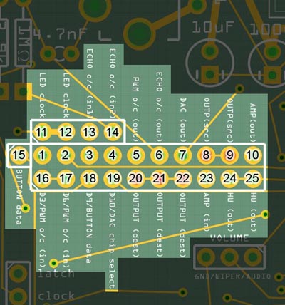
2. Digital Pin 6
3. Digital Pin 9
4. Digital Pin 10
5. PWM Out Circuit (Output)
6. ECHO (Mozzi) Output Circuit (Output)
7. DAC (Output)
8 & 9. OUTPUT (Source)
10. AMP (Output)
11 & 12. LED Clock
13 & 14. ECHO (Mozzi) Output Circuit (Input) – the PWM output from pins 9 and 10 are combined when using Mozzi in hi-fi mode. Here’s the reference circuit.

15. BUTTON Data
16 & 17. PWM Output Circuit (Input) – the PWM output circuit is used for the output of both the Charlie (Illutron) and Delta (Auduino) firmware. It’s taken from this Instructable for the Illutron 4-voice wavetable synth – personally, I find the low-pass filtering of the circuit too heavy handed and always compensate for it with EQ on the desk. I think it should be easy enough to raise the cut-off frequency by replacing the 2.2k resistor with a lower value but I haven’t experimented with it enough to advise a change from the reference design.

18. BUTTON Data
19. DAC Chip Select
20 – 22. OUTPUT (Destination)
23. AMP Input – in my experience, the DAC and PWM outputs are plenty powerful enough to be used with amps, mixers and powered speakers without the need for the on-board amplifier circuit. If you’d like to drive an 8-Ohm speaker directly, however, route the signal through the AMP circuit first. Remember to add a jumper on the 9v header and to raise the input level with the screw on the 10k trimmer (if you have the trimmer oriented as per the build instructions, turning the screw clockwise raises the input level, and anticlockwise lowers it). If you forget, you won’t hear anything.
24 & 15. HARDWARE (Ouput) – the signal that appears on the output jacks.
Pin Usage
With the exception of digital pin 5 (D5) that is not used and is made available on the expansion header (located between Pot 5 and Pot 6), all pins on the Atmega328P-PU MCU are either in use, or broken out to the options header. If a pin that’s broken out to the options header (D3, D6, D9, D10) is not used by the current firmware (ie. there’s no jumper connected to it), that pin can safely be used for other duties.
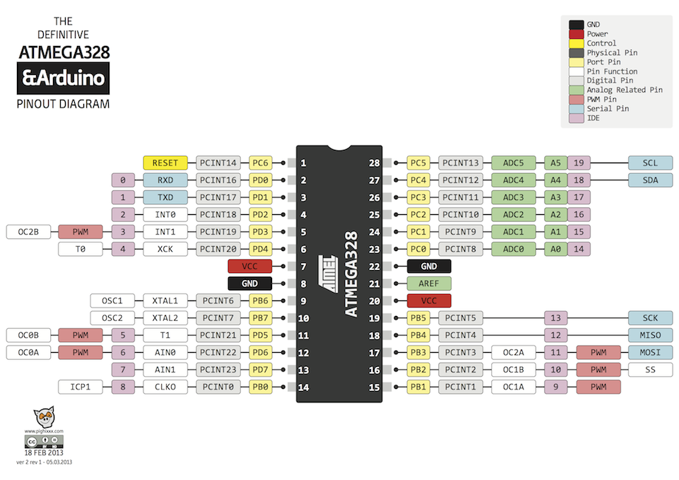
The following pins are fixed to certain duties that do not change between the various firmwares.
D0 (RX) – MIDI Input
D1 (TX) – MIDI Output
A0 – used by the 4051 multiplexer (potentiometers)
D15 (aka A1) – used by the 4051 multiplexer (potentiometers)
D16 (aka A2) – used by the 4051 multiplexer (potentiometers)
D17 (aka A3) – used by the 4051 multiplexer (potentiometers)
A4 (SDA) – used by the Wire.h (I2C) library to communicate with the 24LC256 EEPROM chip
A5 (SCL) – used by the Wire.h (I2C) library to communicate with the 24LC256 EEPROM chip