If you’ve never soldered through-hole electronics before, I suggest you give yourself a quick primer with one of the numerous through-hole soldering tutorials on YouTube, like this one.
Importantly, take all the time you need – there’s no rush. And work in a well-ventilated space.
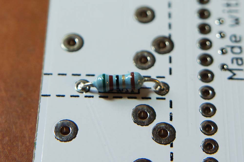
Here’s a general tip regarding alignment of parts. First, solder only one leg of a component. Check the alignment (ie. make sure the component is straight and flush with the PCB). If it’s not, reheat the leg and realign. It’s almost impossible to do this kind of alignment once more than one leg is soldered.
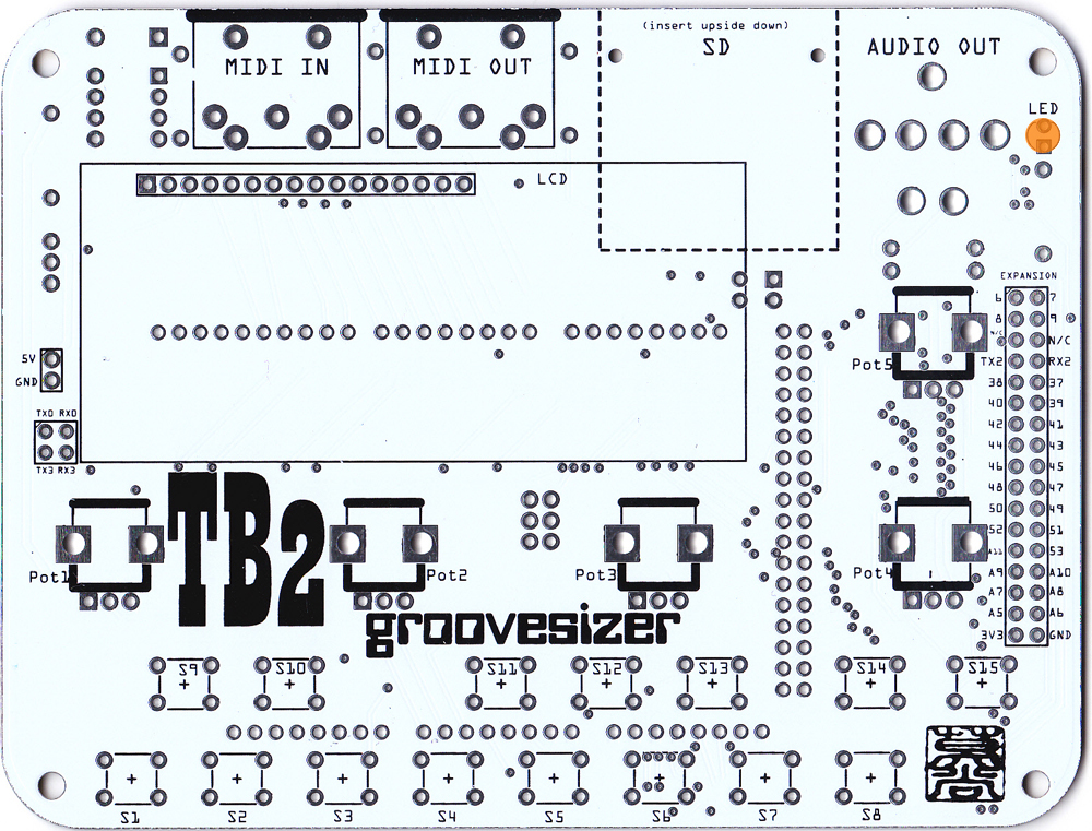
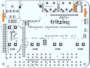
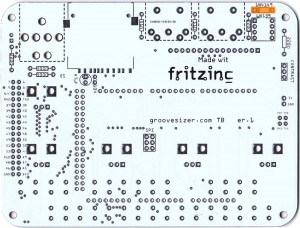
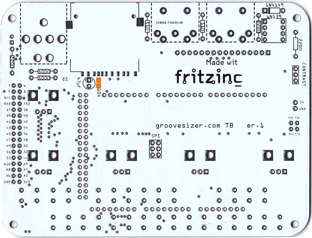
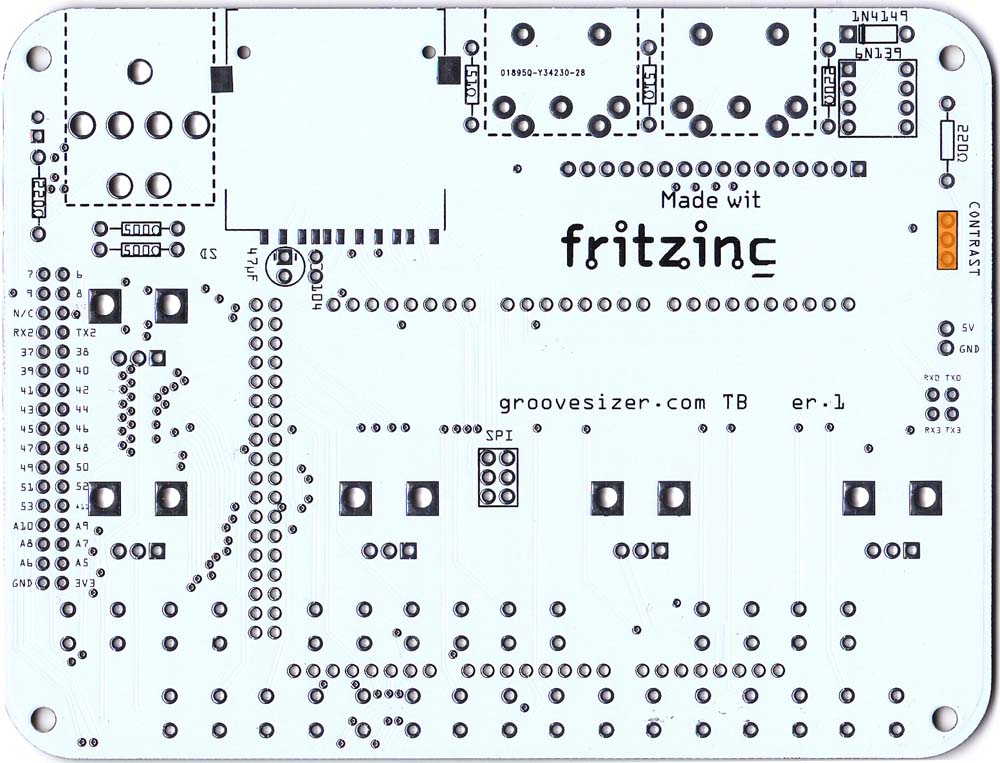
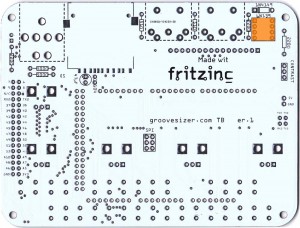
PCB BOTTOM
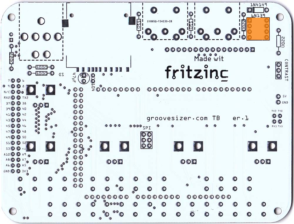
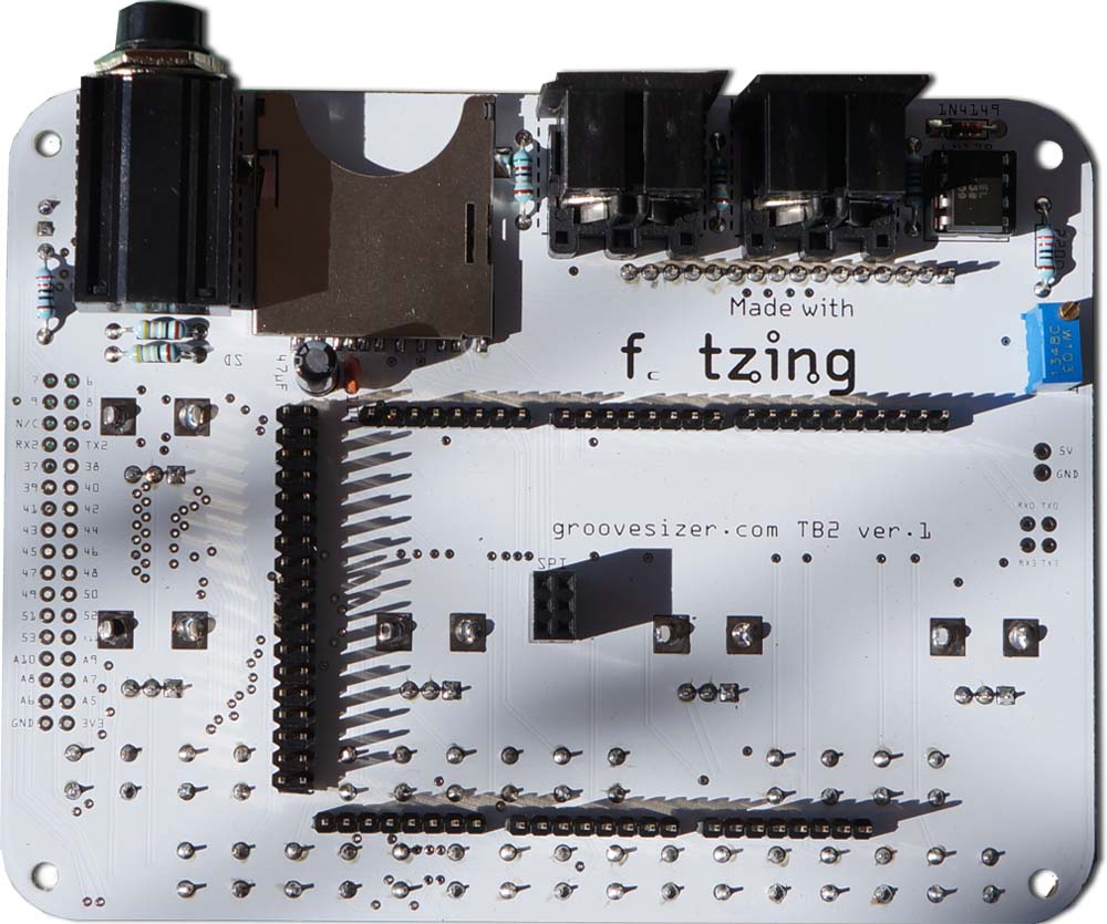
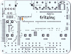
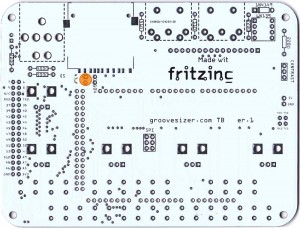
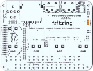
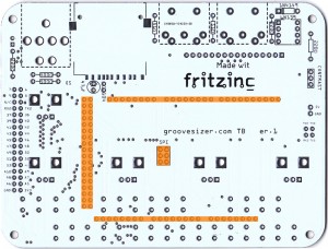
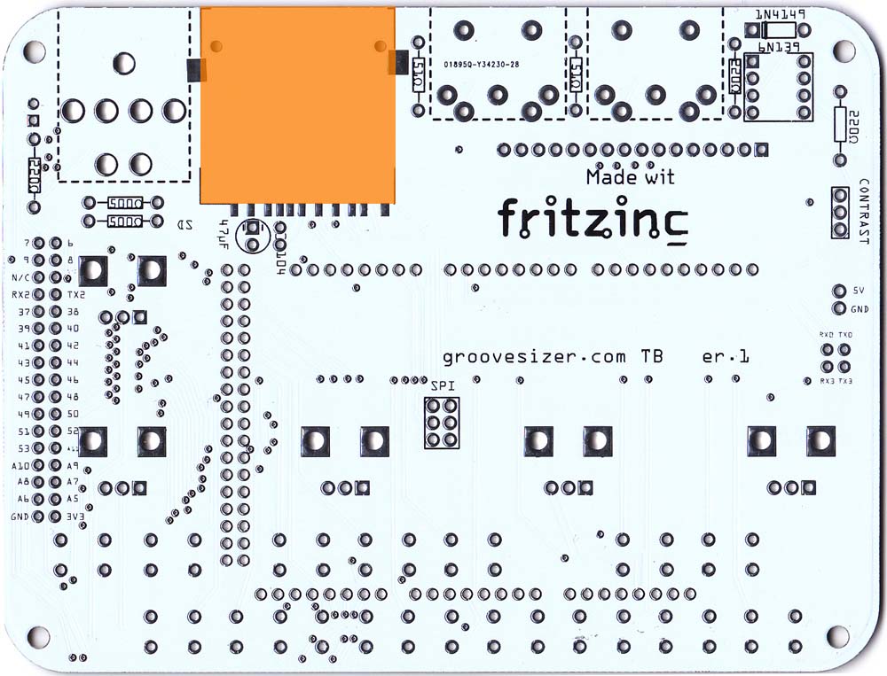
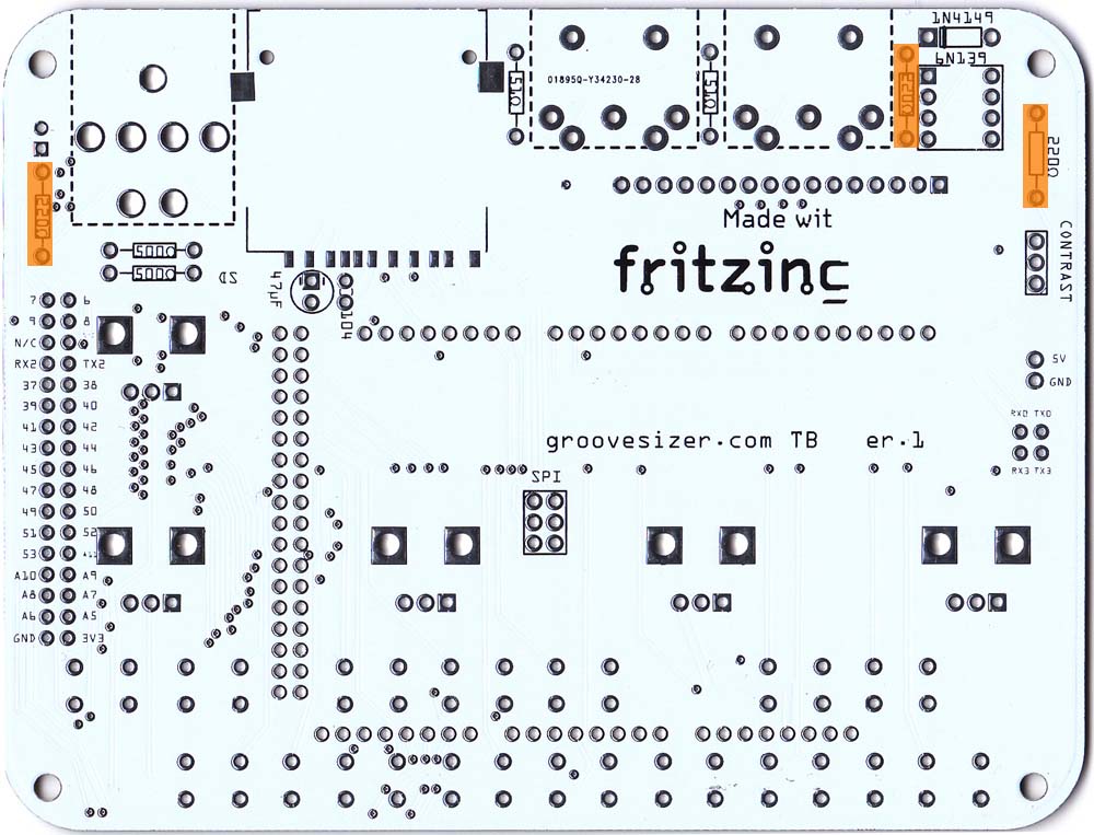
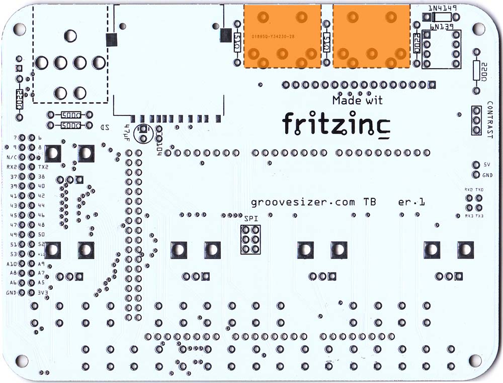
We’ll populate the bottom of the board first – it’s the side with the Fritzing logo. Here’s a shot of the completed bottom of the board for reference (click on any of the images to enlarge them.)
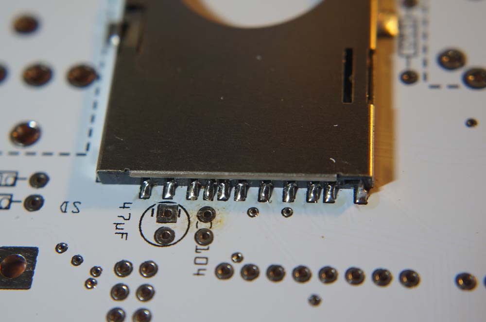
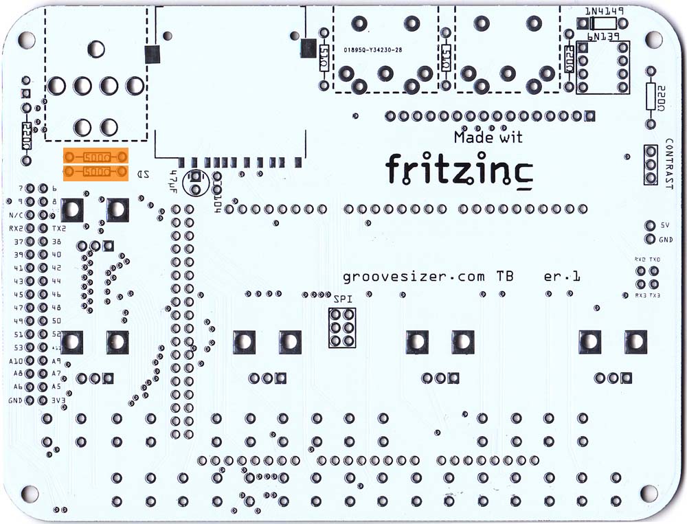
- SD Card Slot We’ll start by soldering the SD card slot to the PCB.
 First, add a small amount of solder to one of the anchor pads. Heat the pad with your soldering iron, and touch your solder to the hot pad.
 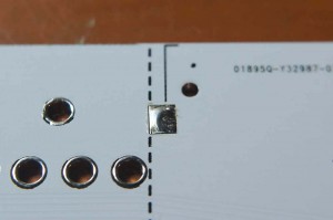 Place the SD card slot on the PCB. Check that the two locators find their holes on the PCB, and that the pins line up nicely to their pads at the back before heating the solder and attaching the slot to the PCB. When you’re happy with the alignment, solder the anchor pad on the opposite side,
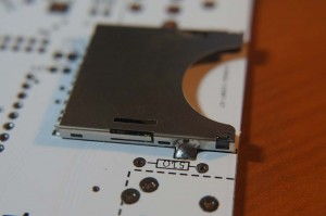 and the pins at the back. This might well be the trickiest part of the build, so take your time (and hold a steady hand).
  Heat the pin and the pad at the same time, and feed in a tiny amount of solder. It’s possible that you manage to bridge two of these fine pins. If you do, use some solder wick to suck up the mistake.
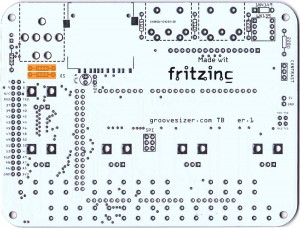
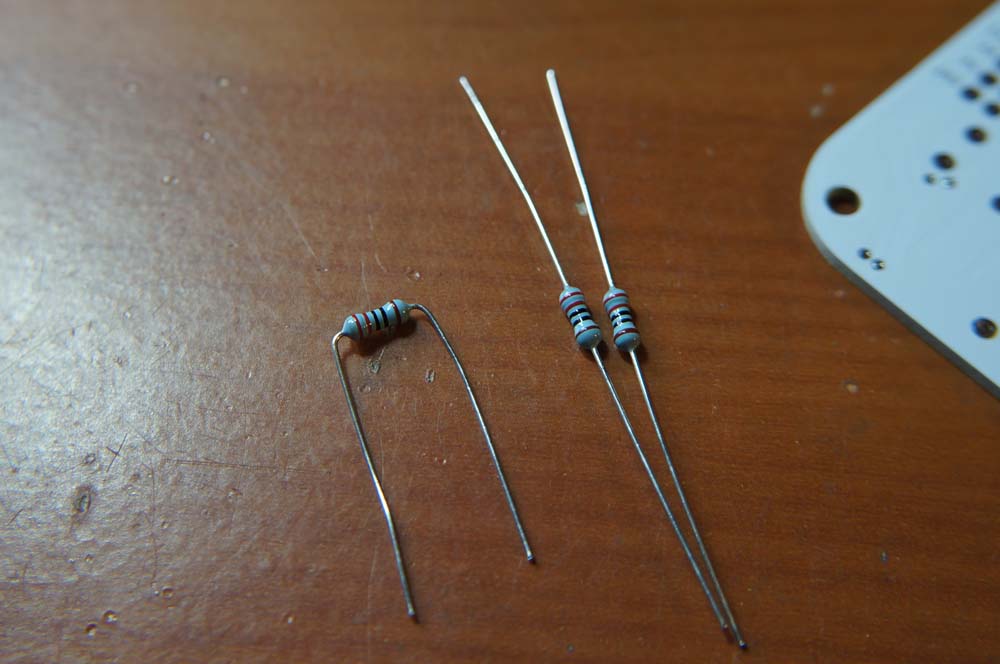
- Resistors Next we’ll add the resistors. They’re not polarized, so it doesn’t matter which way around they go in. Actually, you can populate all the resistors, as well as the diode in step 3 and solder them all in one go.
- 220Ω (x 3) (red, red, black, black, brown). Two of these are used by the MIDI input circuit, and the other by the LED.
 Bend the legs of the resistor into a staple shape,
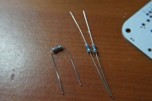 and insert into the board. Bend the legs over at the back so they don’t fall out when you flip the board over to solder.
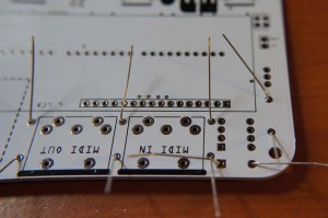
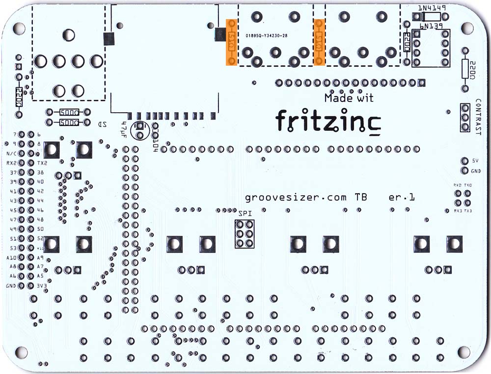
- 499Ω (x 2) (yellow, white, white, black, brown)
 The board has these marked as 500Ω, but 499Ω is close enough.
 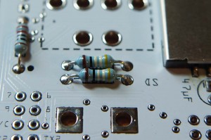 They’re there to protect the DACs on the Due.
 - 51Ω (x 2) (green, brown, black, gold, brown)
 These are used by the MIDI output circuit.
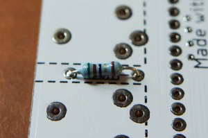
- 220Ω (x 3) (red, red, black, black, brown). Two of these are used by the MIDI input circuit, and the other by the LED.
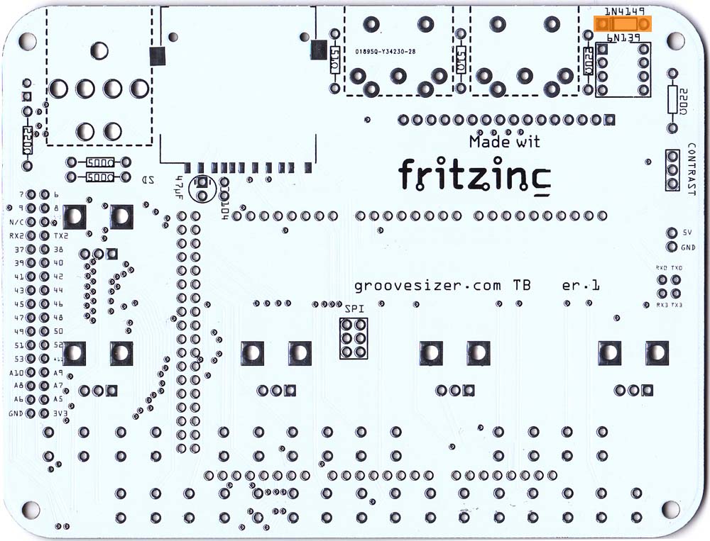
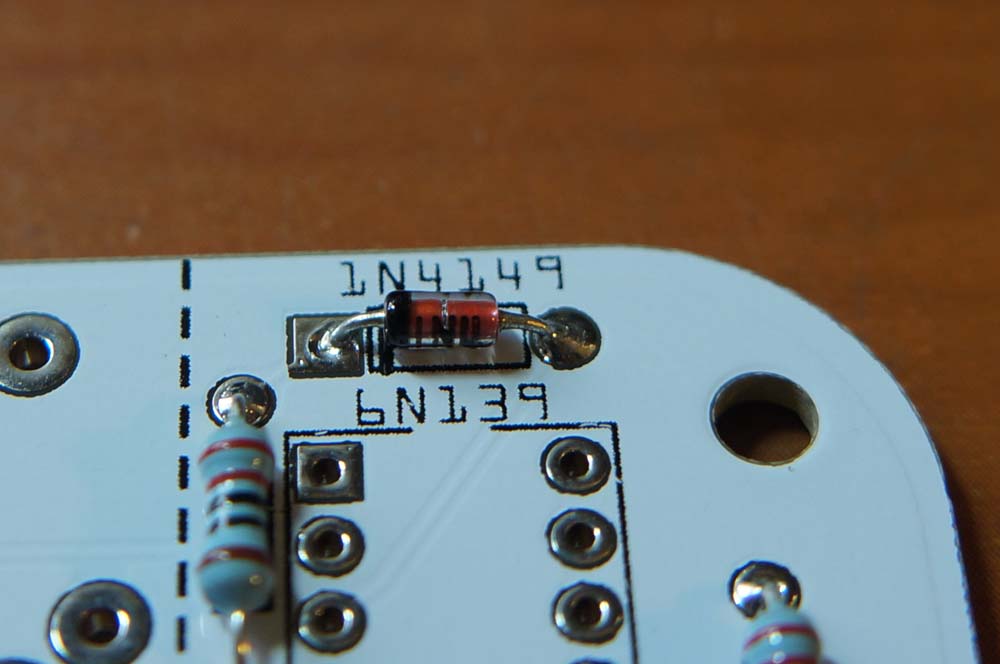
- Diode 1N4148 Oops, it’s mislabeled as 1n4149 on the board.
 Be a little careful with this guy – it’s polarized and can only go in one way around.
 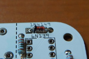 The black line on the one end of the glass body should go on the side marked with a thicker black line on the PCB. Once the resistors and diode are all in, flip the board over and solder. Then, snip off the excess legs.
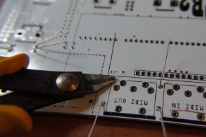
- Capacitors (x 2)
- 104 (0.10uF) Capacitor
 This one’s not polarized, so it can go in either way.
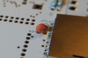
- 47uF Capacitor
 Watch for polarity on this one. The white (or gold) line marked with minuses on the side of the cap indicates ground.
 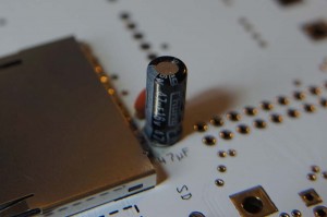 On the board, the ground side’s pad is square and there are two white lines on either side of it.
- 104 (0.10uF) Capacitor
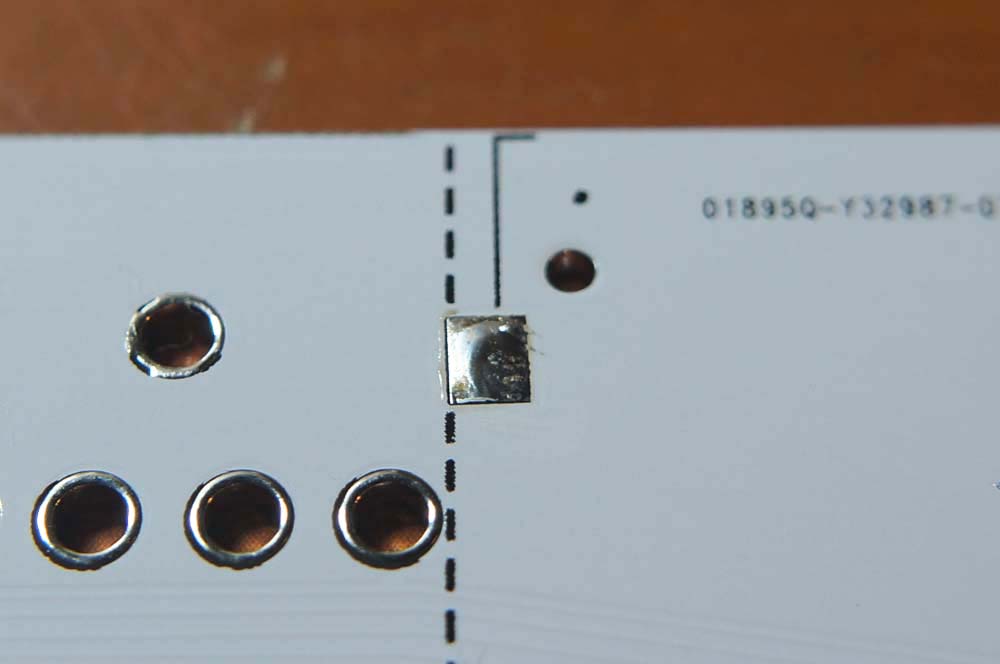
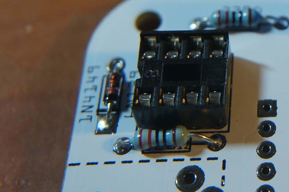
- 8-Pin DIP Socket This is for the 6N138 optocoupler which we’ll fit later.
 The side the notch goes is marked on the board by a broken line on the ICs outline.
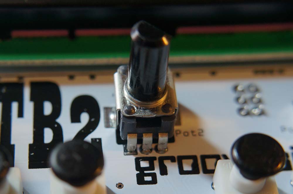
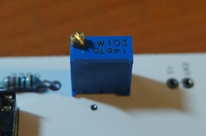
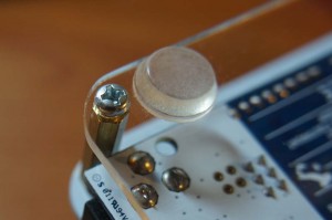
- 10k Trimpot The trimmer is used to adjust the contrast of the LCD display.
 The side with the copper screw is closest to the just-soldered DIP socket.
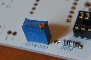
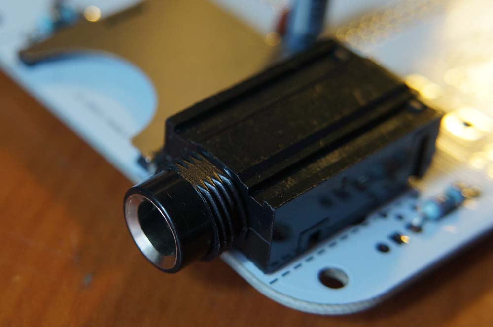
- 1/4″ Jack The audio output.
 The part we received is a slightly updated design with four little plastic nubs for positioning it on the PCB.
 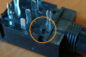 Our PCB doesn’t have locating holes for them, so I suggest just snipping them off with your cutters so the jack can sit flush with the PCB.
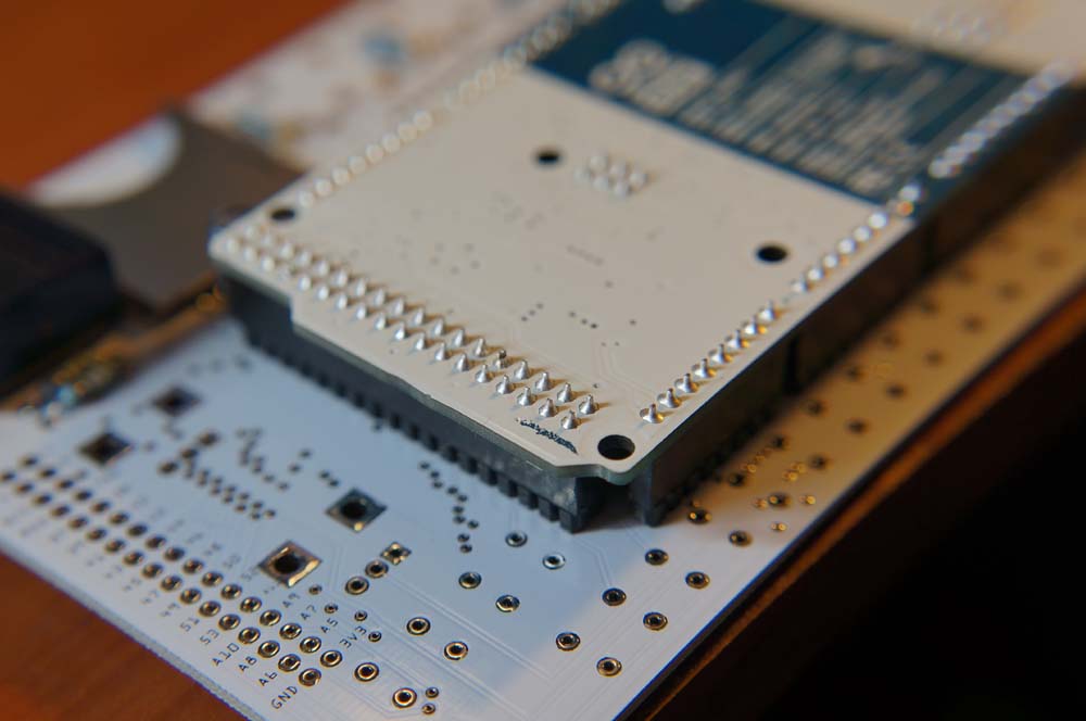
- Arduino headers These allow the Arduino Due to be attached to and removed from the PCB.
 You’ll need to cut the supplied headers to the correct length.
 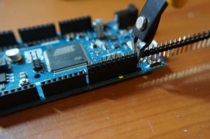 To make sure everything lines up, I suggest placing the headers in the Due board and soldering them onto the PCB attached to the Due. The longer side of the header goes into the Due, and the shorter side will go into the PCB. Don’t forget the 6 pin female header that goes towards the middle of the board.
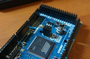
 Just take care when soldering not to linger too long on a pin – you don’t want to melt the plastic shrouding on the Due.
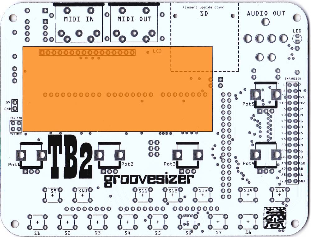
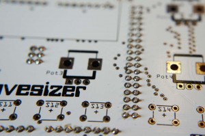 Double check your soldering specifically for the pins that fall in the outline of the LCD. These will be under the LCD, and it’s almost impossible to remove the LCD once it’s been soldered on. After soldering the headers, you can remove the Due board from the PCB. Be careful not to bend the header pins.
 - MIDI DINs (x 2)
 These are for MIDI input and output (go figure!).
 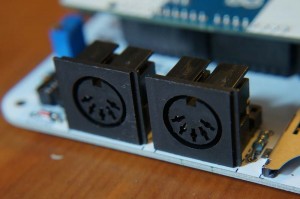 PCB TOP
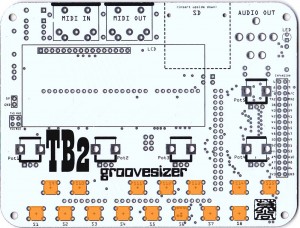
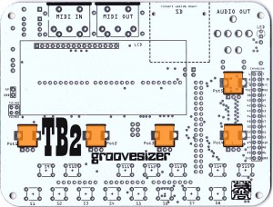


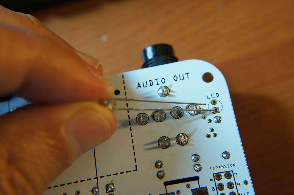
- LED The LED will blink to indicate the tempo, and will also give a visual indication off the LFO shape.
 The LED is polarized. The shorter leg goes towards the top of the board.
  On the board, the pad for the shorter leg is round and the one for the longer leg is square.
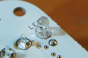
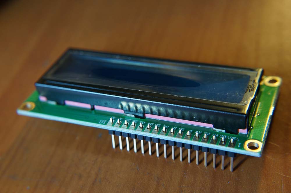
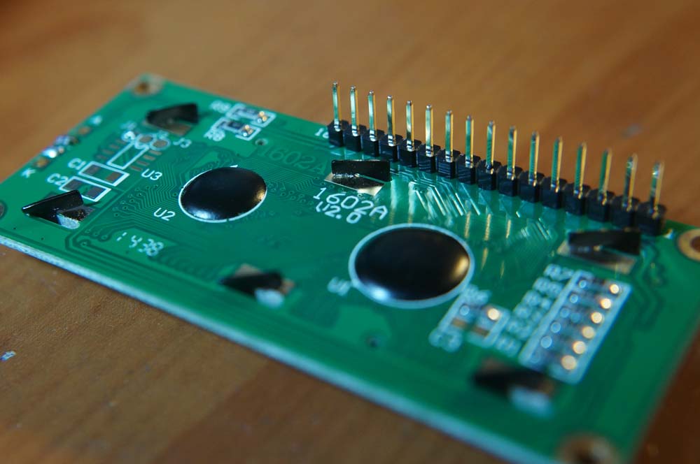
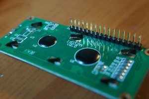
- LCD Next we’ll add the 16×2 character display.
 Start by soldering the header to the LCD’s PCB.
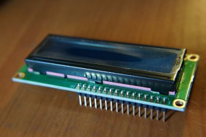
 Then we solder the display to the TB2’s PCB
 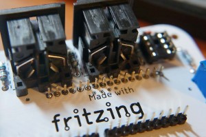 (check the soldering on those header pins again before committing) .
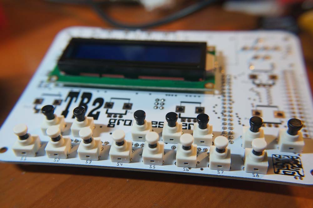
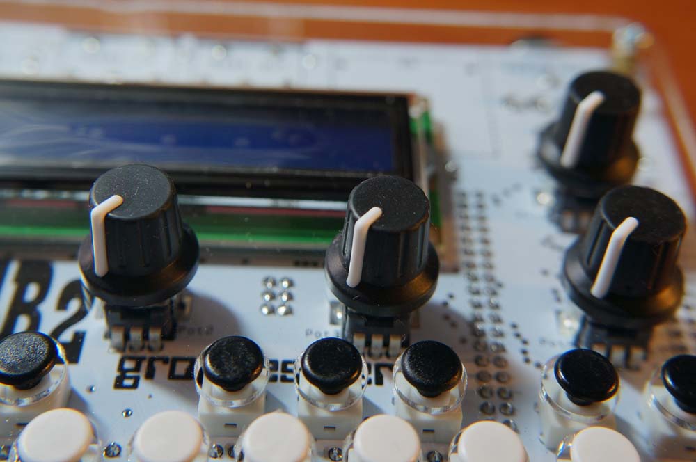
 - Buttons (x 15) We’re adding the tactile switches next.
 The white capped ones are for the bottom row, and the black ones for the top.
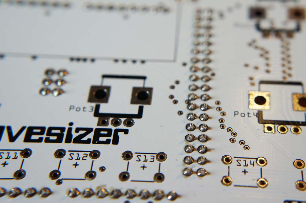
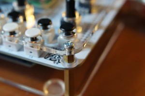
- Potentiometers (x 5)
 Nothing tricky here, but remember to only solder one leg at first so you can straighten the pot if needs be.
- Seat the optocoupler.
 Push the 6N138 (oops, mislabeled as 6N139) optocoupler home into the 8 pin socket.
 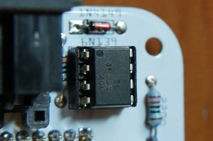 The corner with the dot is on the top left.
 - Reattach the Arduino Due.

- If you received an Arduino Due clone from us with your kit, the firmware you selected on checkout will be pre-loaded on the board (no firmware flashing necessary). If you chose the NoDue option instead and are using your own Due board, upload the TB2 firmware now if you haven’t done so yet (see the Firmware & Resources page for more details).
- Adjust the contrast trimpot.
 With the TB2 powered on (the LCD’s LED should be lit), turn the screw on the trimpot until you can see the characters clearly. If you see all white blocks, you’ve gone too far and you need to turn the screw anticlockwise. NOTE: If you have bought one of the Arduino DUE clone boards from us, remember to press the red reset button on the DUE after plugging in power and before you adjust the contrast. If you don’t, you won’t see characters on the display, put a top row of solid blocks. See here for more details.
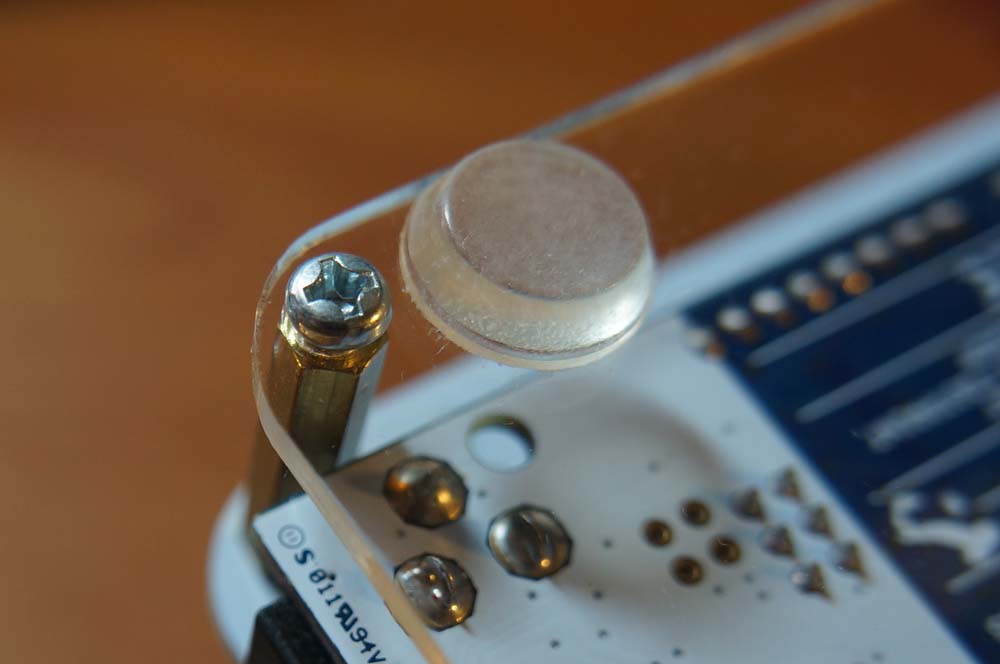
 - Screw in the hex spacers (x 8).
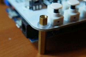 The long ones go at the bottom of the PCB, and the small ones at the top. Add two nylon washers per corner between the small spacer and the PCB.
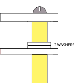
- Screw in the bottom plate and stick on the bumper feet.
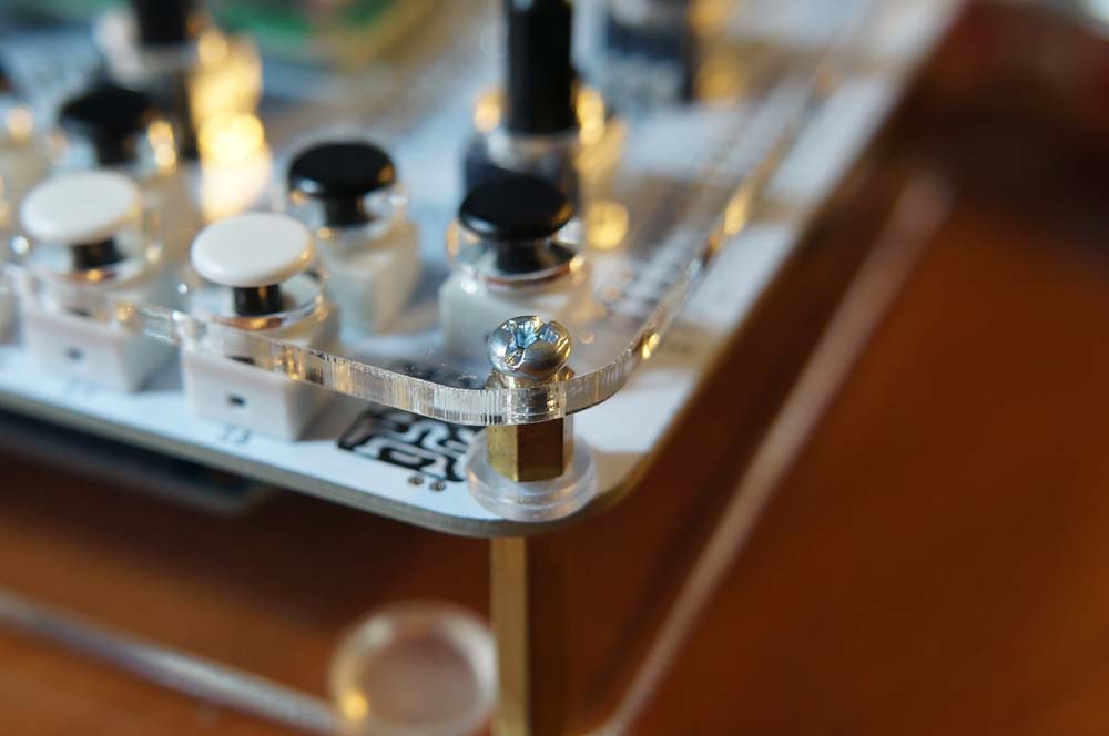
- Screw in the top plate.
 The notch at the back lines up with the MIDI input.
 - Push the knobs onto the potentiometer shafts.

- All done!